I didn't have anything specific in mind to make this week, so I decided to experiment with laying up different degrees of curvature. I also wanted to try creating models from Mathematica. Mathematica is a programming language for mathematical solving and visualization. It has tons of support for mathematical functions and structures, and it also happens to support a huge number of 3d formats. This article has a lot of information about specifically getting stl output from Mathematica.
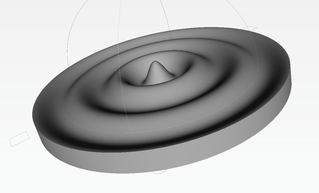
For composites week, I decided to make a mathematical surface. I started by plotting a Bessel function in Mathematica an saving the output as an STL. The process was dead simple:
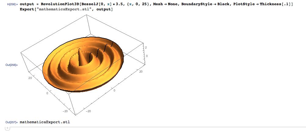
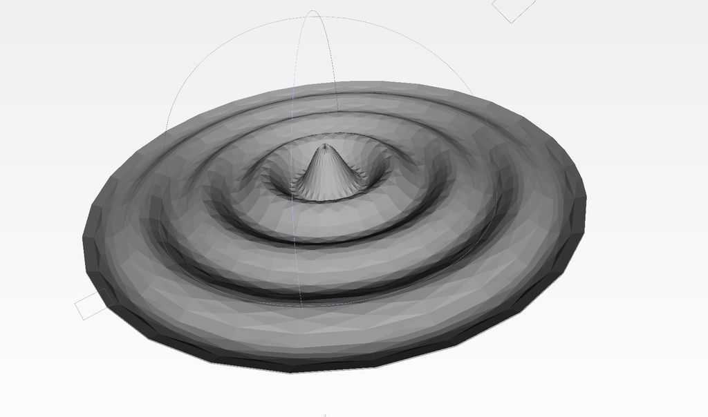
Unfortunately, I couldn't find the information I needed to increase the resolution of the STL output. By default, the output had a lot of visible facets.
Eventually I started from scratch in Processing using the Modelbuilder library for STL output. I've used this library quite a bit for other projects, including 3D Printed Records, so I'm pretty comfortable with it at this point - if you're coming straight from something like Solidworks, it will take some getting used to. Here is the code:
import processing.opengl.*;
import unlekker.util.*;
import unlekker.modelbuilder.*;
import ec.util.*;


int samplesPerRevolution = 200;
float maxR = 3*TWO_PI;
int radialSamples = 200;
float sigma = 30;

float dim = 12;

float baseHeight = 2;

void setup(){

  UGeometry geo = new UGeometry();//place to store geometery of vertices
  UVertexList nextList = new UVertexList();
  UVertexList lastList = new UVertexList();

  float r;
  for (r=0;r<maxR;r+=maxR/float(radialSamples)){
    nextList.reset();//clear old data

    for (float theta=0;theta<TWO_PI;theta+=TWO_PI/float(samplesPerRevolution)){

      float x = r*cos(theta);
      if (x<-dim) x=-dim;
      if (x>dim) x=dim;
      float y = r*sin(theta);
      if (y<-dim) y=-dim;
      if (y>dim) y=dim;

      nextList.add(x,y,1.3*cos(r)*(exp(-pow(r,2)/sigma)+0.5));//cos * gaussian
    }
    nextList.close();

    if (r==0){
      geo.triangleFan(nextList, true, true);
    } else {
      geo.quadStrip(nextList,lastList);
    }

    lastList.reset();//clear old data
    lastList.add(nextList);
  }

  nextList.reset();//clear old data
  for (float theta=0;theta<TWO_PI;theta+=TWO_PI/float(samplesPerRevolution)){
    float x = r*cos(theta);
    if (x<-dim) x=-dim;
    if (x>dim) x=dim;
    float y = r*sin(theta);
    if (y<-dim) y=-dim;
    if (y>dim) y=dim;

    nextList.add(x,y,-baseHeight);//draw egdes of 3d shape
  }
  nextList.close();
  geo.quadStrip(nextList,lastList);
  geo.triangleFan(nextList, true, false);

  geo.writeSTL(this,"math.stl");
  exit();

}
More info is in the docs, but essentially the idea is that geometry is stored and exported from a UGeometry object. There are many ways to get geometry into UGeometry, but my favorite is to use the quadstrip() method on two sets of UVertexLists. I build this model by starting at the center and moving out radially, creating a new UVertex list and quadstripping it to the existing geometry as I go.
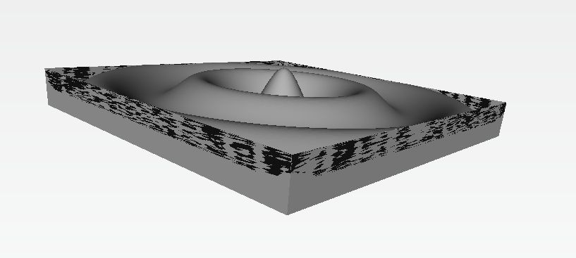
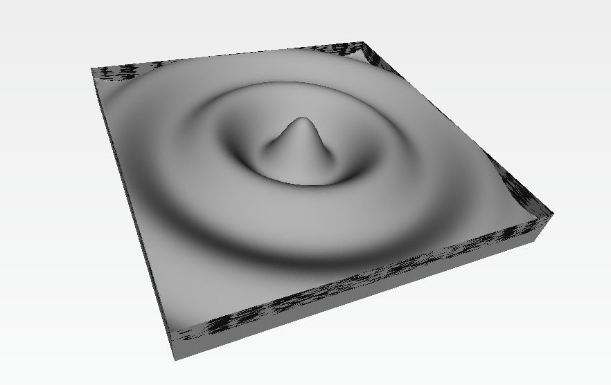
Now I have complete control over the angular and radial resolution, and I was able to add a solid base to the bottom of the surface. There wasn't an easy way to plot a Bessel function in Processing, so I used a cos multiplied by a gaussian instead. I tried pulling this model into solidworks as solid geometry so I could trim it into a square shape, but ran into some trouble because it had too much geometry for solidworks to handle. Eventually I added the lines:
    if (x<-dim) x=-dim;
    if (x>dim) x=dim;
    float y = r*sin(theta);
    if (y<-dim) y=-dim;
    if (y>dim) y=dim;
So that the trimming happened in Processing instead. This was not the cleanest way of doing things (though it was the easiest), so I ended up with some extra faces around the edges with 0 dimension. Partworks was fine with it, so I left it as is.
I processed all my files in Partworks3D to generate my toolpaths for the Shopbot. Here are the files:
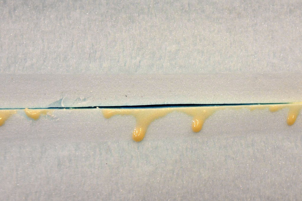
I started the layup process by gluing two pieces of foam together with gorilla glue. I tried my best to clamp the piece down while it dried, but it looked like there were still some gaps between the two pieces of foam.
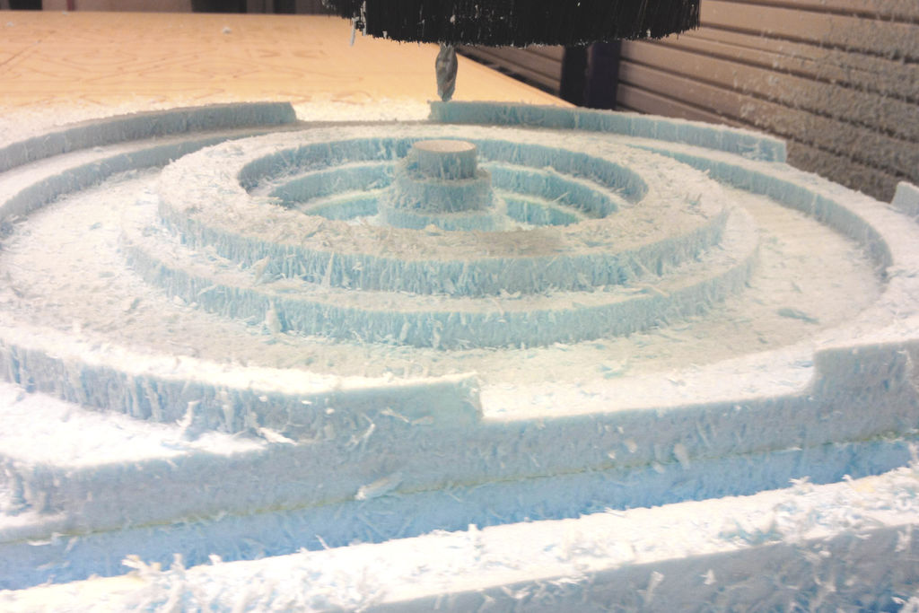
I did my rough cutting with a 5/8" end mill on the shopbot. A few of these passes cut all the way into the bottom layer of foam, and to my surprise, all my seems looked good. I guess the foam did make good contact where it counted.
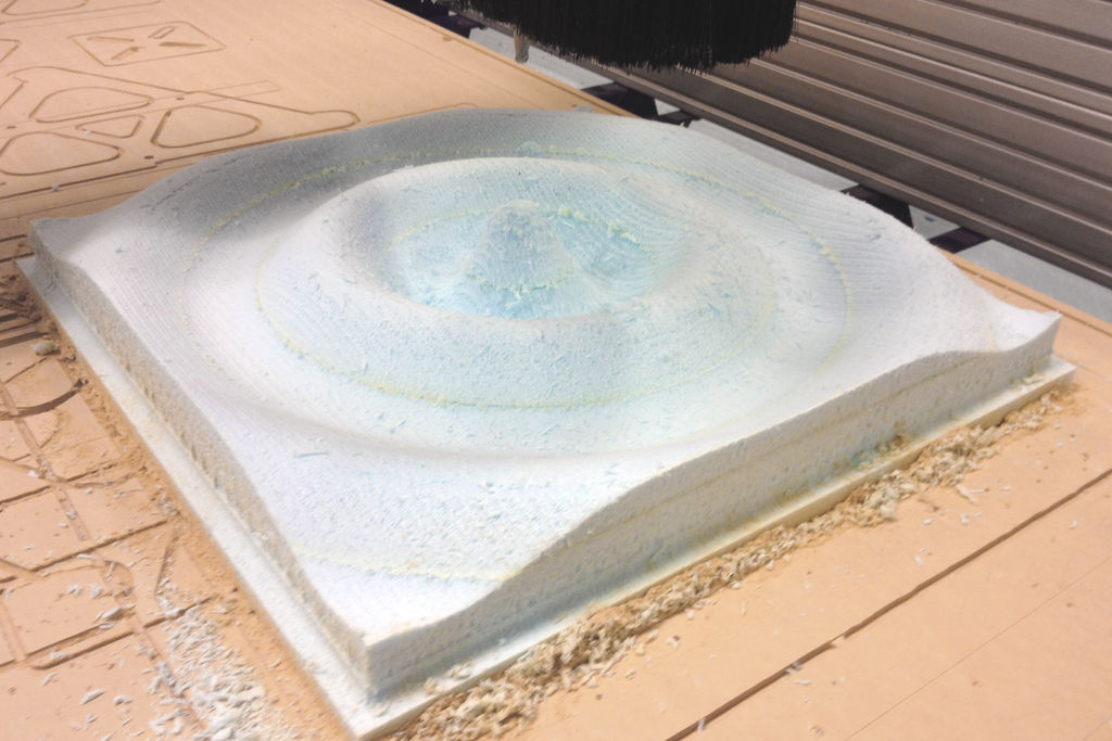
I did a finish pass and cutout with a 1/2" ball end mill, seams still look good.
I went over the foam with some sandpaper to make it nice and smooth, then I applied a coat of epoxy. My plan was to use wax on the foam as a release - to prevent the burlap from bonding to it - so that I wouldn't have to use the pink release film (and hopefully get a better finish on my piece). Unfortunately, I reached for the clear epoxy instead fo the regular epoxy. The clear epoxy takes about 24hrs to cure, so when I came back the next day, my foam was still tacky. I waited about 23 hrs, and the epoxy was showing no signs of curing, so I went ahead with the pink release film.
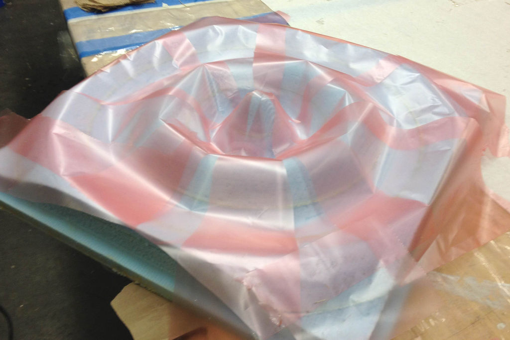
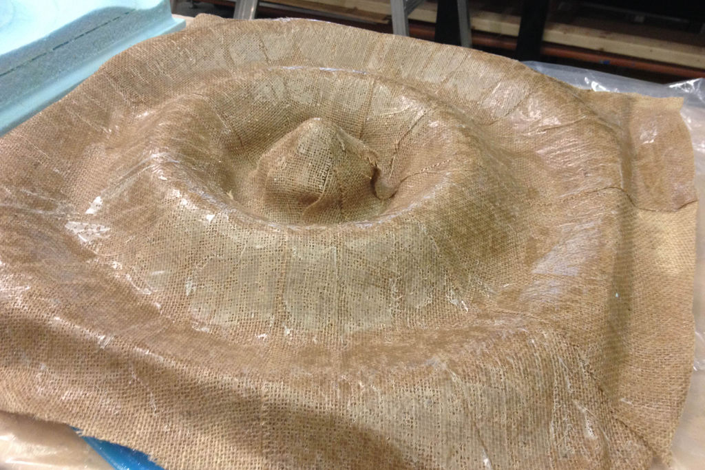
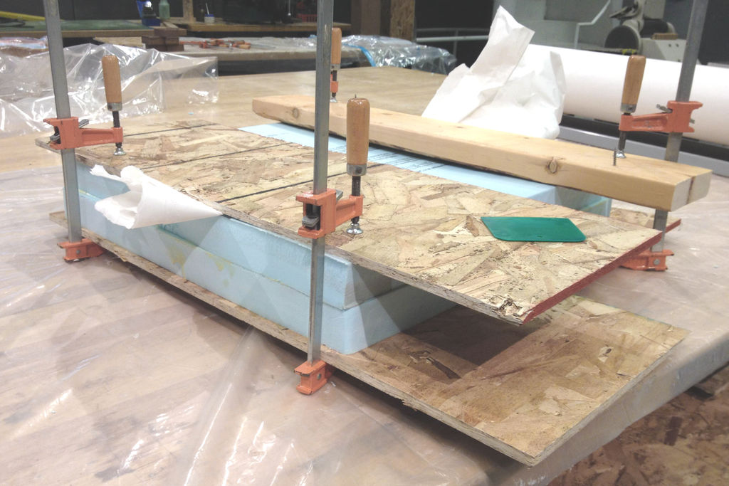
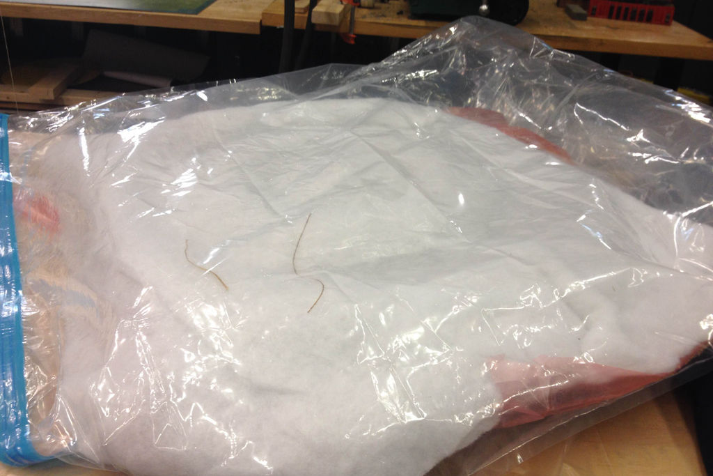
I cut 17 triangular pieces of burlap and laid them up similarly to how the release film is shown in the image above. In the end I had somewhere between 2 and 3 layers of burlap (which was a lot of work for such a large surface) on my mold. I did my layup with the regular epoxy. I used a perforated piece of the pink film as a bleeder and used some of the pillow stuffing as a breather. Then I put the whole thing under vacuum using one of the clothing vacuum bags and a shopvac.
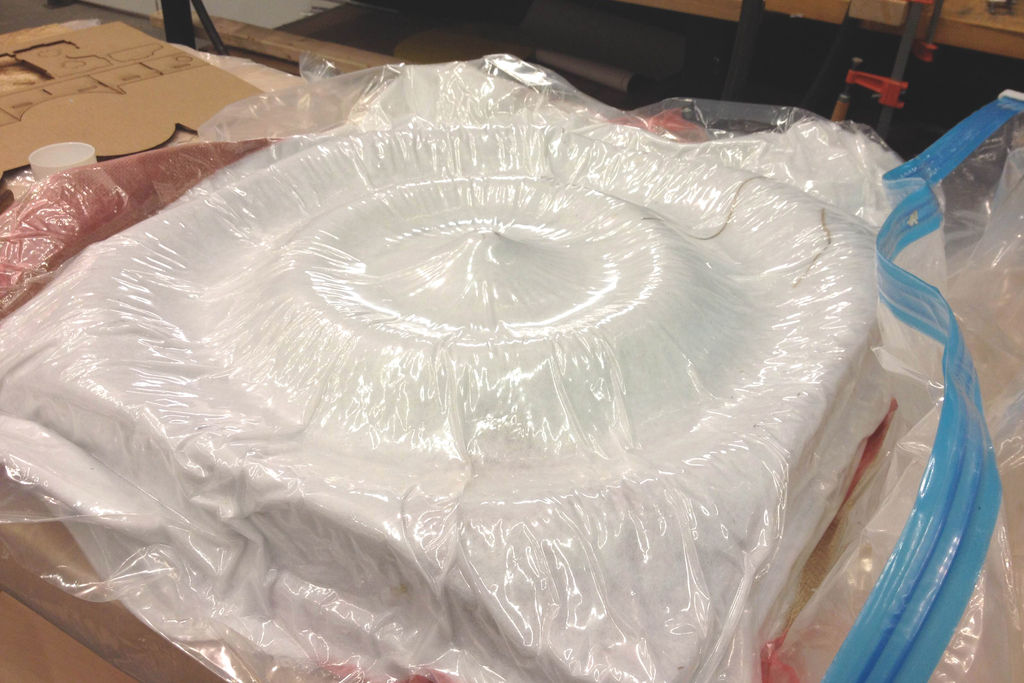
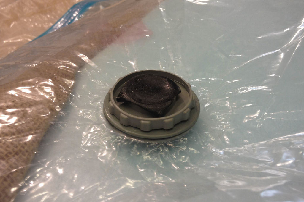
I couldn't find a cap to put on the vacuum bag, so I closed the valve and used some tape to cover it.
Unfortunately, this didn't work as well as I'd hoped. When I came back the next morning the vacuum was completely gone.
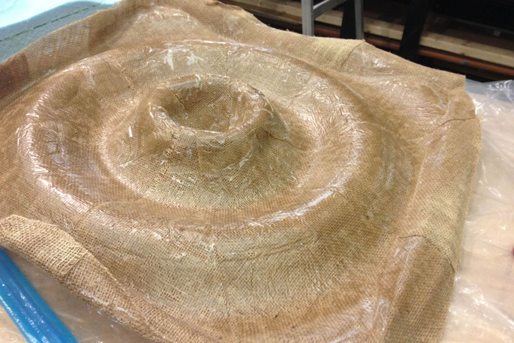
I opened the bag and removed my part, luckily it still came out pretty good all things considered. One thing I would change for next time is to pack more breather into the convex portions of the geometry so that those parts get properly compressed by the vacuum. I think the innermost section of my layup would have come out much better if I'd done this.