This week I took a stab at the main board for my final project this semester. This board controls 4 DC motors and connects to the IMU board from last week as well as a GPS receiver. Once this board is complete, I will be done with all the electronics design for my final project.
PARTS LIST:
Motors:
(x4) A4953 H bridge Digikey 620-1428-1-ND
(x4) 0.22uF capacitor Digikey 399-1251-1-ND
(x4) 100uF electrolytic capacitor Digikey 493-2226-1-ND
(x4) 0.25 ohm resistor 1W, 1% tol Digikey CSRN2010FKR250CT-ND
(x4) Micro Metal Gearmotor with extended Motor Shaft Pololu 1595
(x2) 5V Optical Encoder Pair Kit Pololu 2590
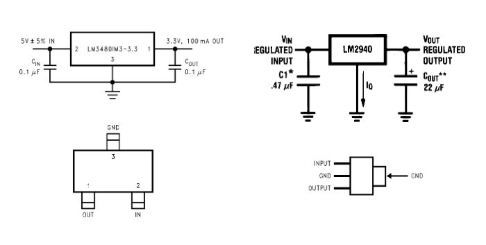
(x1) 3.3V voltage regulator Digikey LM3480IM3-3.3/NOPBCT-ND
(x1) 5V voltage regulator Digikey LM2940IMP-5.0CT-ND
(x2) 0.1uF capacitor Digikey 1276-1017-1-ND
(x1) 0.47uF capacitor Digikey
GPS:
(x1) EM-506 GPS Receiver Sparkfun GPS-1275
(x1) 6 pin connector
Microcontroller:
(x1) Atmega328P Microcontroller Digikey ATMEGA328P-AURCT-ND
(x1) 10K resistor Digikey P10KECT-ND
(x1) tact switch Digikey SW262CT-ND
(x3) 0.1uF capacitor Digikey 1276-1017-1-ND
(x1) 10uF capacitor Digikey 1276-2876-1-ND
(x1) 8MHz resonator Digikey 535-10004-1-ND
(x1) green LED (optional, but will help with debugging) Digikey 160-1404-1-ND
(x1) 1K resistor (optional, but will help with debugging) Digikey P1.0KECT-ND
Interface:
(x1) 6 pin ISP header
(x2) 6 pin female 0.1" header
Other:
(x35) 0 Ohm resistor (jumpers) Digikey P0.0ECT-ND
Milling:
(x1) 10mil carbide endmill Carbide Depot CU 222737 (for the tiniest features on the board)
(x1) 1/64" endmill Carbide Depot CU 129974 (for milling out the traces)
(x1) 1/32" endmill Carbide Depot CU 129985 (for roughing the traces and cutting out the board)
(x1) FR-1 machinable single sided PCB blank Inventables 24201-02
I used a Roland Modela for the milling, though I believe this could be done on a Shopbot Desktop or similar machine as well.
Other Supplies
solder/solder paste
soldering iron
tweezers
multimeter
FTDI cable Digikey 768-1015-ND or board Sparkfun DEV-09873 (you may be able to use an Arduino as an FTDI connector) 3.3V or 5V is fine, but if you are making the IMU board too, you will need 3.3V.
ISP programmer (or use an Arduino or make your own)
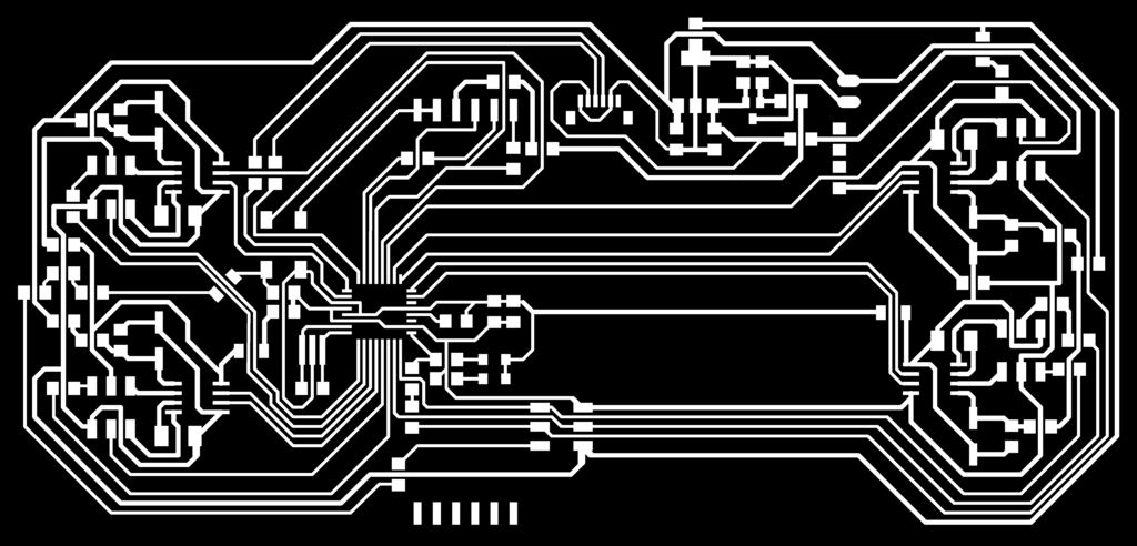
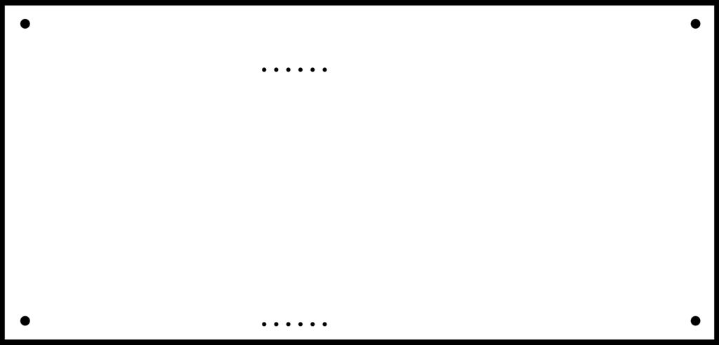
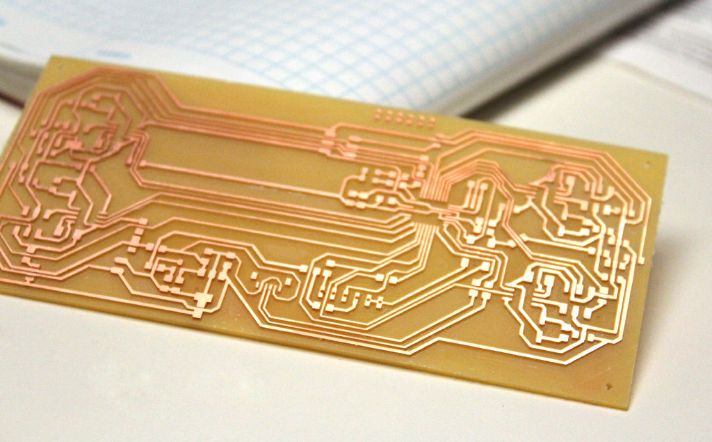
My PCB design is up on Github (click on the cloud-shaped button to download). I ran the file CompassMainBoardTraces.png through the online fab modules to create a roughing toolpath using a 1/32" end mill and a finishing toolpath using a 1/64" end mill and milled the board on a Roland Modela. (a more detailed description of a similar process is here). I ran one final pass with the 10mil end mill to get all the really fine details of the board milled out. Then I cut out the board using CompassMainBoardOutline.png with a 1/32" end mill. (again, see this ible for more details).
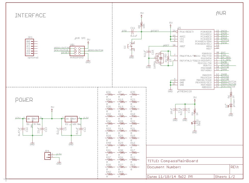
I started populating the board by soldering the voltage regulators and all the jumpers on first and double checking that the output on each of my power rails was correct (12V, 5V, and 3.3V) when the 12V supply was applied to the board.
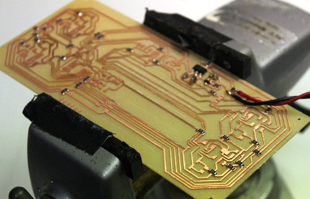
This is when I realized that my motors actually run off a 6V supply and I've designed this board for a 12V supply. Doh! Unfortunately, the 5V regulator needs at least a 6.25 supply, so there wasn't an easy way for me to fix the problem. At this point I decided to redesign my board. This sucks, but the 6V supply simplifies a lot of my power issues because now I can power the GPS with the 6V supply and power the microcontroller and the IMU from 3.3V. I now have no need for a 5V supply, just 6 and 3.3. In this next design, I'm going to make each of my motor controller boards separately and plug them into my main microcontroller board with some right angle headers for extra modularity. I'm going to add a space for a 2.1mm coaxial jack so that I won't have to solder wires directly to my board. I'm also going to mess around with my routing spacing because I'd like to be able to mill my board without the 10 mil end mill.
Here's what I would have done next if I hadn't made that mistake:
Then I added only the components for the Atmega328P (see schematic above) so I could make sure it was working before moving forward.
First I burned the Arduino bootloader on the 328 chip following these directions (one slight difference is that you will want to select Arduino Uno as the Board type instead of Pro Mini). The MISO, MOSI, and SCK pins are also connected to the motor input pins, so if you are having trouble communicated with the chip, be sure you do not have your motors wired up to the 6 pin headers. Then I uploaded a simple Hello World sketch to make sure the Atmega was functioning (again, selecting Arduino Uno as the Board type).
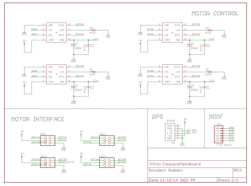
The main purpose of this PCB is to control 4 DC motors with H-bridge circuits. Here's a video that explains what an H-bridge is and how PWM can be used to control speed in both directions:
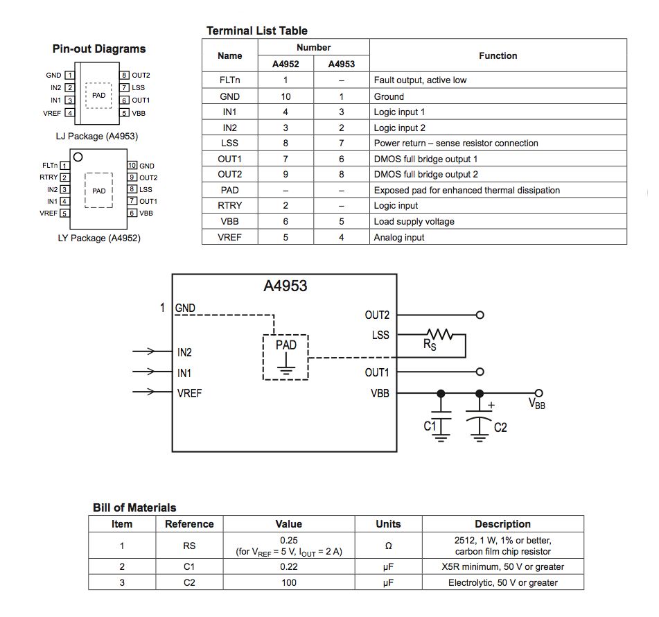
The datasheet of the A4953 H bridge says that it can power brushed motors with supplies up to 40V and peak current output of +/- 2A using either 3.3 or 5V logic. The wiring diagram and pin information for the chip is shown in the image above. The motors I'm using have an extended motor shaft where you can mount an optical encoder. This allows you to get closed loop control over the motors' position and speed. I've hooked these up to the Atmega's digital input pins.
Once the "Arduino" is working, wire up one H-Bridge and test it with a motor plugged into the 6 pin connector. Run the following code to test:
Repeat this with each of the remaining 3 H-bride circuits.
Finally, attach the jack for the GPS module. The GPS module for this board runs off a 5V supply (the reason I couldn't run the whole project off 3.3V!). The Atmega328 communicates with the GPS via two serial pins, on my board the GPS is connected to pins D2 and D3.