![[Image_Missing]](img/projects/project-01a.png)
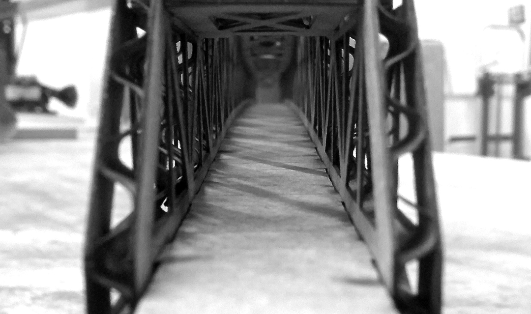
This is the final laser cut model of the Tobin Memorial Bridge, spanning the Mystic River. The model is roughly 750mm long, and barely fit in the laser cutter.
![[Image_Missing]](img/projects/project-01b.png)
It took me a while to decide what to make, and at one point I wanted to make a set of puzzle pieces that one could build 3D structures with. This art structure was one of my inspirations.
![[Image_Missing]](img/projects/project-01c.png)
After deciding on the Tobin bridge, I imported a photo into SolidWorks, and then used that as a rough guide to create the bridge. It was hard to find a photo that was exactly from the side of the bridge, this was the best one I could find. In order to not get a lopsided bridge, I only modeled half of it, and then mirrored the other half. As you can see here, due to the perspective of the photo, the right side of the bridge does not quite match up, but is identical to the left since it was mirrored.
![[Image_Missing]](img/projects/project-01i.jpg)
Instead of worrying about modeling the bent car deck as a sheet metal part, I modeled the connection holes to follow the curve of the car deck, and space the connection tabs with equal distances in the pattern tool. This way I could easily model the car deck flat, model the tabs with the same spacing as for the bride sides, and know that the tabs will fit. Due to the minimum thickness of functional parts in corrugated cardboard, I decided to not model the upper car deck at all, since the sides of the bridge would have to be almost solid (to allow sufficient room for the connection tabs), which would not look aesthetically very pleasing. When actually cutting the bridge out of the corrugated cardboard, it was important to think about the directionality of the corrugations. For the road section, I had the corrugations going perpendicular to the bridge, to make it easier to create the bend of the road deck.
![[Image_Missing]](img/projects/project-01h.jpg)
I tried to make the model as parametric and use as few measured dimensions as possible. The top trusses for example were just linked to the cross beams, so modifying the distance between the connection tabs in the pattern would automatically adjust the top truss dimensions. The vertical dashed lines were used to score the cardboard for the sharp bends in the top section of the bridge. The 5mm dimension makes sure that the bend does not coincide with a truss.
![[Image_Missing]](img/projects/project-01d.png)
When the model was complete, and I was ready to start laser cutting cardboard I first made a few test pieces to figure out the optimal gap size. My model would be joined with friction fit slots, so getting it just right was important.
![[Image_Missing]](img/projects/project-01j.jpg)
When I was getting ready to cut my part and was zeroing the laser cutter, on two instances the gantry (the moving part with the laser head on it) of the machine slammed hard against the hard stops at the edge of the machine. The confusing part was that I had performed the zeroing operation (at least in my opinion) exactly as before, without any problems. After talking with two separate TA's, the conclusion was that it was probably a problem/bug with the machine itself. The way that the problem occurred was when I had placed the laser in the correct position and then hit the 'set home' button. Most of the time it set the location correctly as the home location, but sometimes it would start to scroll some text on the display. – If one then hit the 'set home' button again the laser cutter would slam the gantry against the side of the machine.– The TA's recommended to just press 'cancel' or shutting down the machine and then restarting it if this happens again.
![[Image_Missing]](img/projects/project-01e.png)
Due to the number of tabs involved, it was a little finnikey to get the parts to connect. It helped that the tabs had chamfers on the edges, and that all the measurements were correct.
![[Image_Missing]](img/projects/project-01g.jpg)
Top view of the trusses.