Week 1: Dice Tower (Laser Cut Construction Kit)
Concept
This week’s assignment was to make a press fit construction kit with a laser cutter. I also took it upon myself to learn some more extensive CAD modeling in SolidWorks in preparation for the rest of the semester.
I decided to make a dice tower, which is used in board gaming to roll many dice simultaneously so that they don’t fall off the table. I wanted a stable structure, and attempted this by using a few pieces that were bent in three-dimensional space.
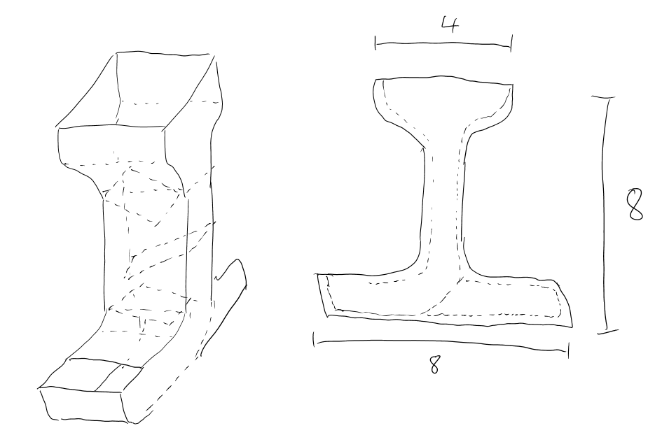
I began with a drawing of the concept of the tower, which would have an enlarged top for ease of throwing dice into, several ramps to redirect the dice, and a rollout area at the bottom to collect the dice.
Design
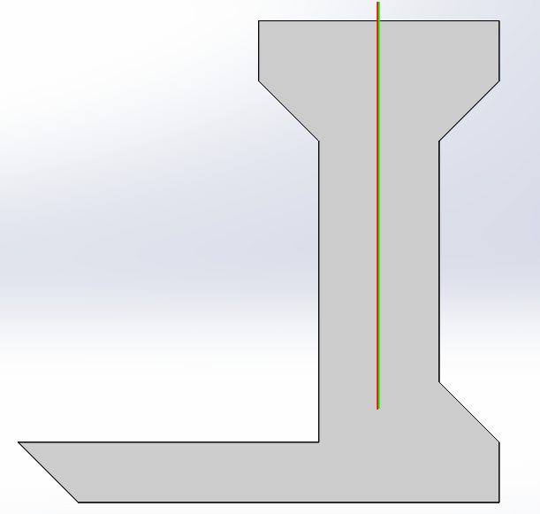
I first started by designing the sides of the structure, because the other pieces would slot into them, and they would determine the size of the rest of the structure. After seeing the shape I initially sketched out in a CAD tool, I decided that the rear wouldn’t need to be as large and it would be better to have a big tray in the front. The basic side of the tower ended up with the following shape:
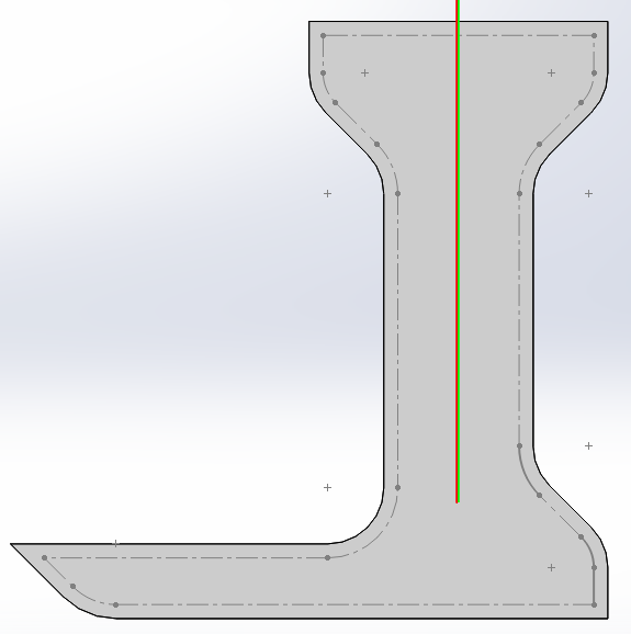
After adding fillets to round out the edges, I faced a significant challenge in correctly placing the slots in the structure. First, I spent some time learning about global variables and equations in SolidWorks so that my cardboard thickness and slot size would be properly generated for press-fit construction. Second, I learned about generating offset lines in sketches, and construction lines which stay in the part for future features. After adding some fillets and the offset lines, the part looked like the following:
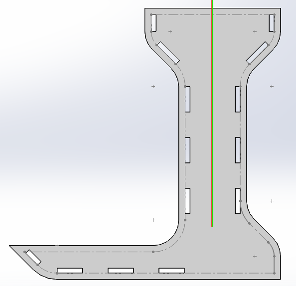
This allowed me to place slots that were offset an even amount from the edge, even along curves:
Finally, I created another set of lines, offset from the first, that represented the paths of the front and rear walls along the side. Importantly, this path would be measured to create the final lengths of the front and back walls. Without this path, it would have been very difficult, if not impossible, to get the walls to be the right size in one piece of curves.
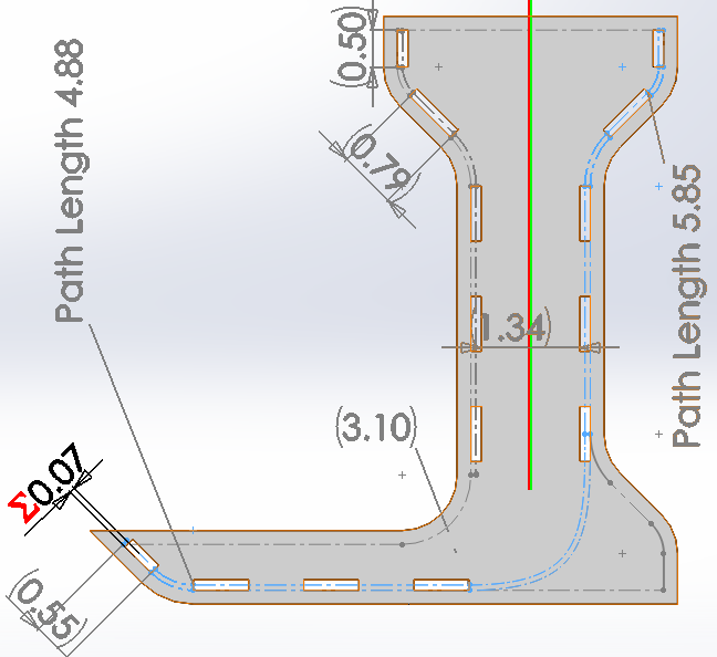
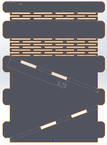
Armed with the paths computed previously, I got to work creating the front wall, as it was simpler than the rear. The patterns you see are flexures - more on that in a bit. Each tab is filleted to have a round corner for easier construction, and has a height of twice the thickness of the cardboard. I tested the ramp angle with some dice on cardboard and hand-waved a value that wouldn’t have the dice get stuck. This resulted in room for only two ramps.
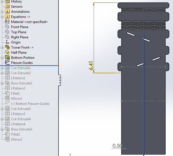
Finally, I got to work on the more complicated rear wall. Just as I was about to redo all my work for the front wall, I realized that SolidWorks allows one part to be the base for another part. I took the front wall and just extended it downward the right length to get a good starting point for the rear wall. Since the top parts of both are the same, this was quite a time saver.
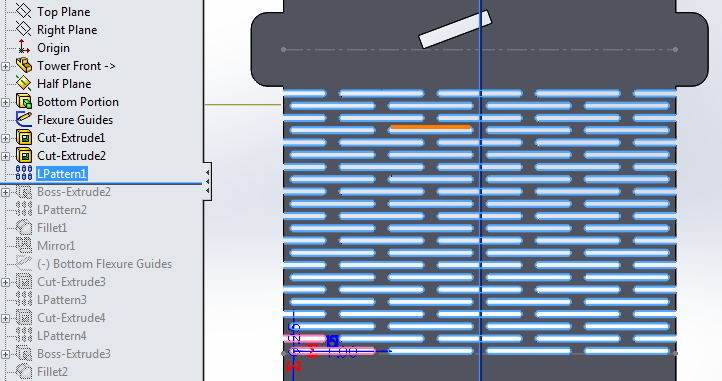
I had seen examples of flexures in past course assignments, but had to figure
out how to cut it myself. SolidWorks has a Fill Pattern feature that I spent a
lot of time trying to use, but it turns out this isn’t quite what is needed for
cutting shapes that aren’t symmetric. I discovered that the most efficient way
was to make two slots cut offset from each other, and then extend both of them
in two dimensions with a linear pattern.
At this point it was basically smooth sailing to complete the pieces. The ramps were much simpler to create.
Over this whole process, I spent a lot of time agonizing over how to create flat parts for printing that could be bent appropriately for modeling purposes. It turns out there are basically two ways (that I can tell) to do this in SolidWorks. The first is to create a part with bends, and have different configurations depicting its bent and flat state. The second is to design the part with the bends, and use the sheet metal tools to flatten it out and obtain the flat profile. It would have been difficult to add flexures to a bent part, and because I was confident of my measurements, I decided to just leave this exercise for the future. Here’s what the assembly looks like without the proper bends. Kind of silly, but it was useful to verify that everything was around the right length.
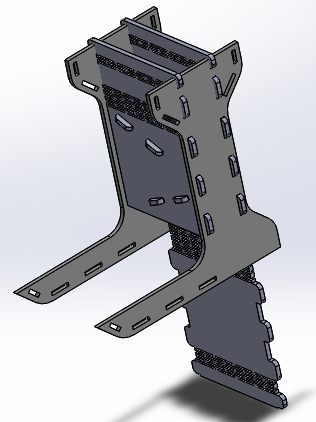
There are a lot of pictures in this section. I used the rollback feature in SolidWorks to generate the partial designs for each part, so I didn’t have to document as I was actually figuring things out.
Cutting
Figuring out how to cut properly was a bit of an ordeal, as the Harvard shop hasa different laser cutter that could not directly use the MAS 863 fab modules tocompute an offset tool path. As a section, we tried a lot of different ways to convertSolidWorks output to an appropriate format, but failed to find a reasonablesolution. In the absence of being able to interface directly with the printer, the most straightforward method seems to be to print out a SVG or high-resolution PNG that is a drawing (not a path) of the part to be printed, and then to use the fab modules to output a SVG that represents a tool offset path, and to print that. The number of conversions involved in this process was becoming horrendous. I decided to go ahead with cutting and see how it would work, as cardboard is a relatively forgiving material.
To obtain the thickness of the cardboard and of the slots in my model, I first
measured the thickness of several pieces in different locations with calipers
and came up with a value of 0.165 in. I then squeezed the calipers a bit and
saw that it could go as low as 0.145 in. For a snug fit, I set these as the
variables in my model.
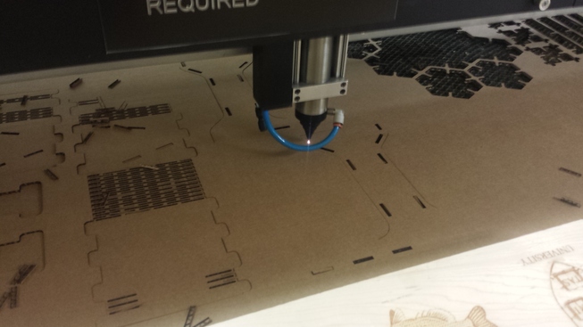
The actual cutting process was a bit intimidating, as SolidWorks had basically exported a series of unrelated lines for each segment of each piece. This resulted in the printer cutting parts rather randomly, starting some parts before finishing others, and cutting outlines before finishing small details such as the flexures. I was worried that some details would be cut in the wrong place, and when returning to the origin after finishing, the laser head actually caught on the piece and moved the whole thing. Luckily, I dodged the bullet this time!
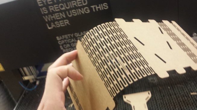
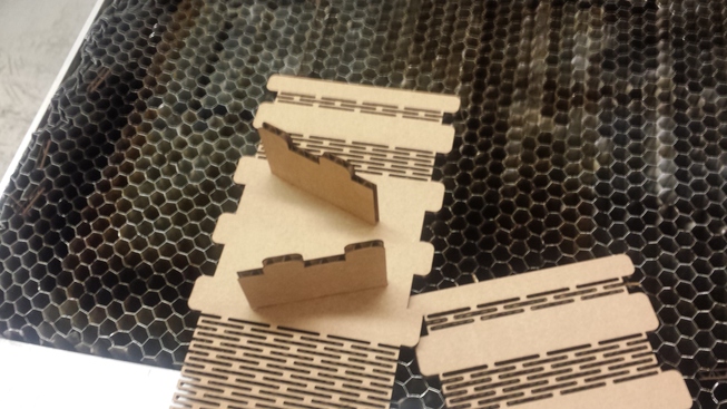
First flexure I’ve ever made! I’m holding it, and gravity is producing a nice curve. Seems to work well!
Here are all the parts.
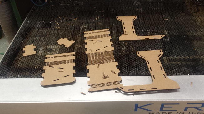
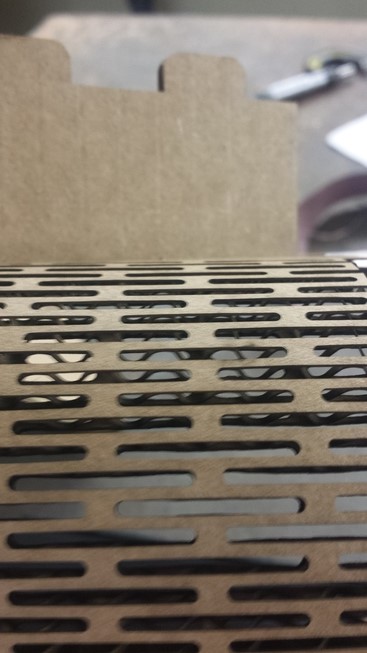
Cutting flexures with small slots shows two interesting details, as in the
picture below. First, I had to cut the flexures perpendicular to the corrugation
in the cardboard. This meant that each small piece would be attached from top to
bottom. Because the flexure size was smaller than the “wavelength” of the
corrugations, there would be many parts where the middle corrugation was cut out
completely otherwise. Second, in the picture, you can also see the effect of not
offsetting for the kerf. In the model, the slots and the ribs are meant to be
the same size of 1/16 (0.0625) in, but the slots are noticeably bigger. This
is accounted by the laser kerf of about 0.01 in.
It turns out that I had probably created a press-fit kit that was too tight with the measurements above. Luckily, ignoring the laser kerf meant that the tabs were cut slightly smaller and the slots were cut slightly bigger, and assembly went just about perfect, with parts snug but not too tight. It took a while to put together the pieces as they had to be bent properly with all tabs inserted at the same time, but I had survived the hard part now.
Finally assembled! Note how the front and rear are one continuous piece, and bent at the point of flexures.
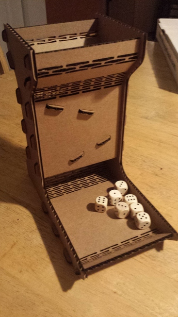
And here’s the final product, doing its job. Not a great dice roll, though.