Week 2: PCB Fabrication
This week’s assignment was to create a surface-mount PCB from scratch. This includes milling it out from raw PCB stock, and soldering surface-mount components on to the board. The first thing that stuck out to me when I got to the lab was that the board was much smaller than I had imagined. A firm hand and delicate motions are helpful for this assignment.
The first step was to cut out the standard PCB using a provided image and the fab modules. People who were already familiar with this could have designed their own version of the PCB from scratch, but I decided to just stick with the assignment as I had never done anything beyond basic through-hole soldering before. Even so, setting up the mill for this requires some care. First. the board stock needs to be attached with double-sided tape to a flat, clean surface, as the copper layer to be cut is very thin and needs to be as flat as possible.
Then are the end mills we’ll be using, which are 1/64 in and 1/32 in. For
someone who has only seen large HSS metal machining bits before, these are
tiny. They are ceramic coated SiC, and are pretty brittle - if you drop one,
it’ll be done. Be very careful handling them, as the most likely place to drop
them is in the process of attaching to the collet.
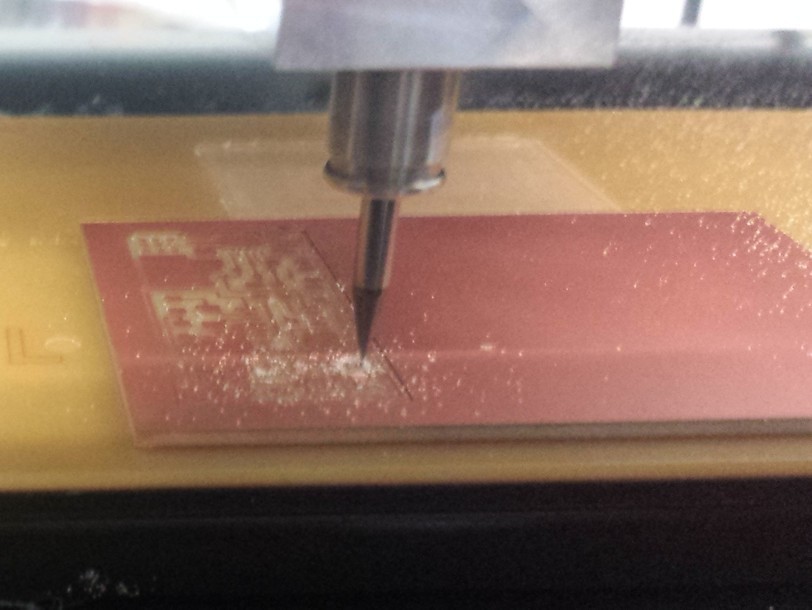
Installing the end mill in the Roland MDX-20 is a careful balance of having the mill be as far into the collet as possible (to minimize flex in the shaft) and to still have some room in the z-axis (to mill the board, especially in finally cutting it out). I ran into a mistake where the mill reached the bottom of its z-extent, and the board outline was just cut in 3 identical paths as the machine could no longer move downward. Luckily, this was easily fixable by simply adjusting the z-axis upward and re-zeroing the end mill.
The milling process is otherwise pretty painless and takes about 10 minutes:
Next comes the long and potentially arduous soldering process. I’ve only worked with through-hole parts before, and surface-mount parts are much smaller. They need to be placed with tweezers, and are very easy to lose. Having a vise to hold the board above the table is very helpful.
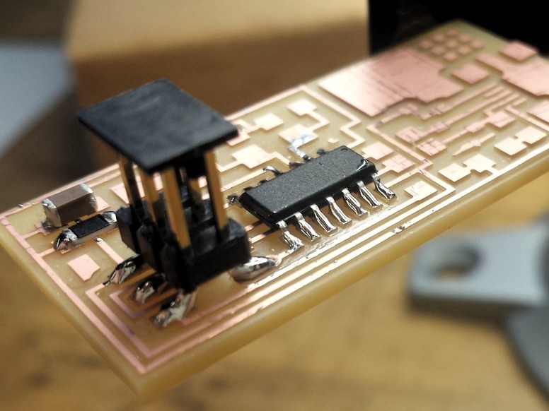
The trick to soldering is to heat both the pad (trace) and the part with the
iron, and add just enough solder to have it flow over both pieces. Here are my
first few tries with the legs of the ATTINY44. The joints are nice and shiny,
which is apparently the way they should be. I find that it’s helpful to hold my
breath and exhale slowly while soldering, as it helps to steady my hand and also
clear the fumes that are generated.
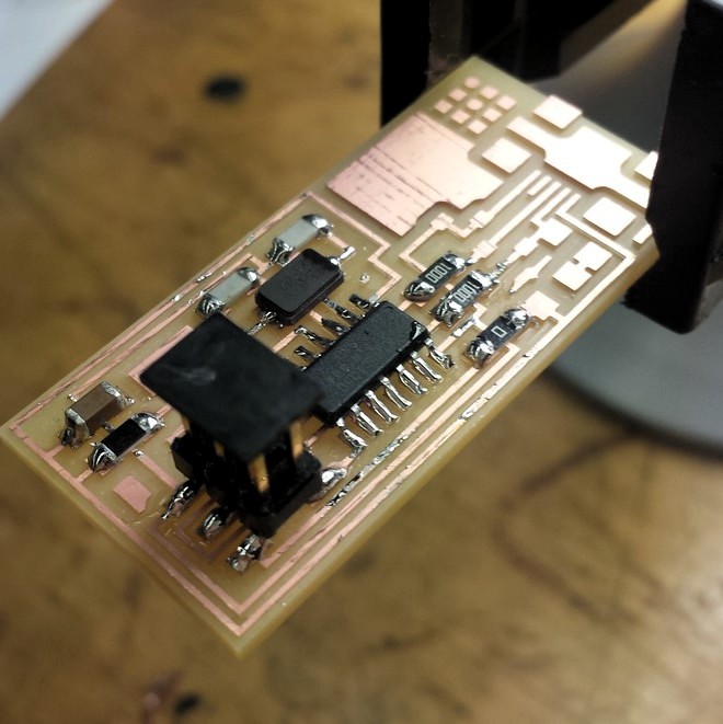
I’ve continued to add more parts. There are some interesting features on this board - in particular, the 0-ohm resistor (just a wire) that is used to bridge two traces. Some of the blobs of solder are slightly bigger than I’d like, so I’ll come back to clean them later.
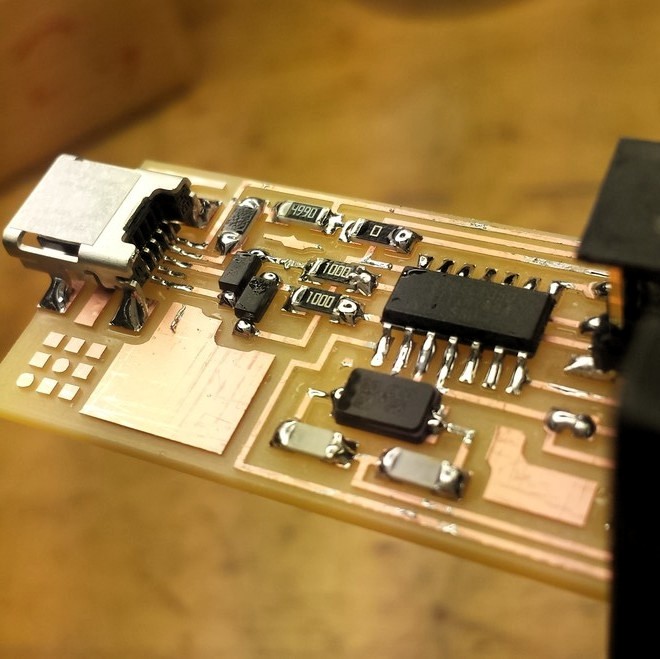
This is the final board. Time for some cleanup! The tool for this is the copper wick, essentially a roll of thin copper strands that can be applied to any blobs of solder and heated with the iron, soaking it up with its increased surface area.
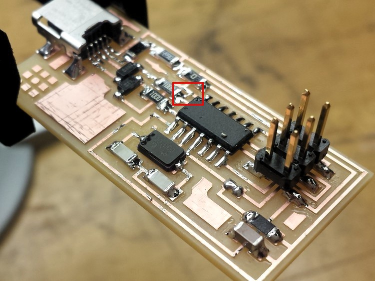
The image below shows many of the solder joints cleaned up. However, I had some problems programming my board after this, and after some careful inspection I realized that the wick cleanup had created an intentional bridge between two traces, highlighted in the red rectangle below. After fixing this up, I was good to go.
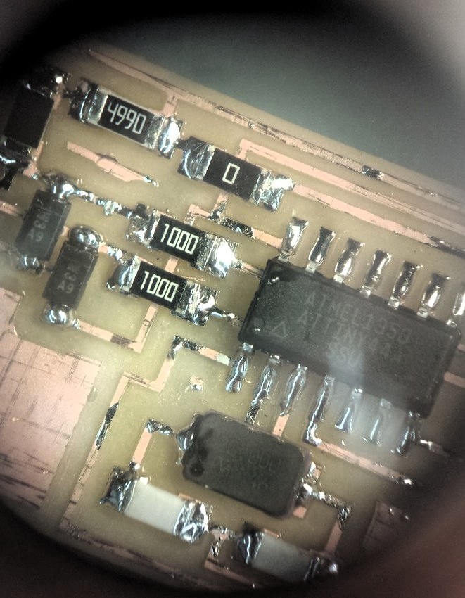
The following image shows a picture of the traces after being cleaned up, taken through a microscope. Microscopes are very useful for inspecting small solder joints!
After all of this, I washed the board with soap and water to clean up any flux, dust, or oils. The board should be ready to go for the rest of the class!