Week 4: Foldable Table Tennis Training Net (Make Something Big)
The inspiration for this week’s assignment is a training or catch net for table tennis. These are useful for practicing serves, or for multiball training when practicing certain strokes. The net conveniently catches balls in a wide area and provides an easy way to retrieve them. Our club currently doesn’t have one of these, and so much training time is spent picking balls off the floor, as they really go all over the place.
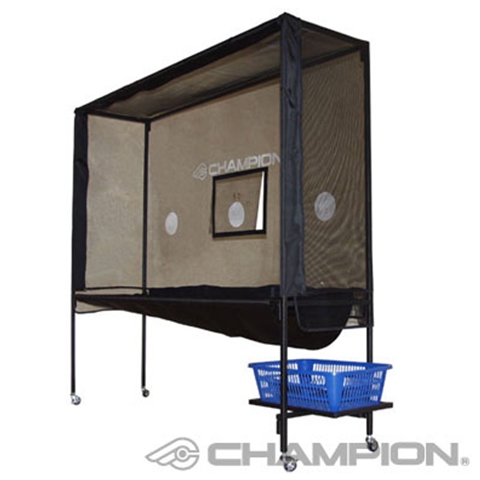
The problem with the catch net is that is very large, designed to be wide enough to fit around the table and tall enough to catch both high and low balls. A table tennis table is 5 feet wide, and most good catch nets are almost 6 feet high. So while it certainly fits the bill for something that would be big to make, I also don’t want it to be too unwieldly.
As a result, I decided to explore designs for the net that would be collapsible, or at least take up much less space when not in use. This feature would also be desirable at my club, as there is not much space to store a large structure. After turning over several ideas in my head, I finally settled upon the following design, and made some hand sketches to envision how it would work.

At a high level, the net is a rectangular structure that folds up in the two axes that take the most space, with arms collapsing in the directions noted at the top left. Angle brackets will be used on joints to restrict the degrees of freedom, so that the net doesn’t fall over when it is unfolded. Joints will use bolts with nylon lock nuts, and large washers to prevent the wooden arms from rubbing directly on each other. Most importantly, the arms will need to be carefully positioned in different planes so that they can move past each other during the folding process.
At this point, it became hard for me to mentally picture the different pieces of the structure, so I got out the CAD tools. The first order of business is a sketch of all the arms from the front perspective.
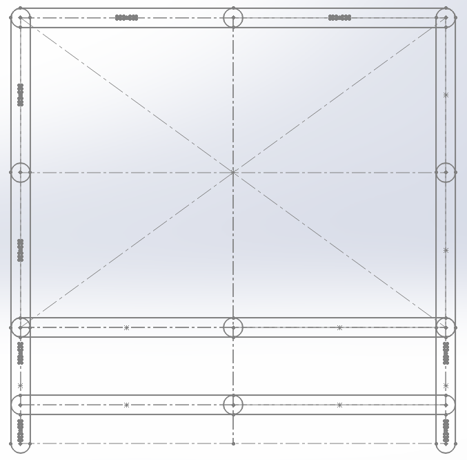
The net has beams that connect the front and rear of the structure. For the mating joints of these beams, I decided to use the blocks feature of SolidWorks, which are basically sketches that can be repeated in different places and are linked so that they can be edited simultaneously. This shows two female joints, which are designed to be press-fit (actually, more like mallet-fit).
Because the arms rotate past each other in different planes, I laid all of these out relative to the origin. There’s no need to do this for the back side as it is just a mirror of the front across a particular plane.
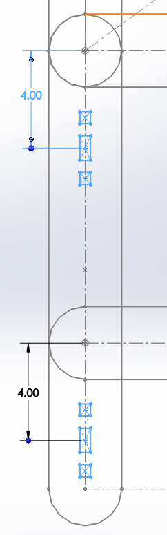
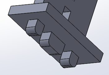
This shows one foot of the net, with a male and female press-fit joint. The strange design is due to my plan to attach a caster wheel on every foot, which has a threaded bolt end that needs to be screwed in to the leg. The rectangular part will hold the leg together and prevent the wood from splitting, so that the bolt will be nice and snug.
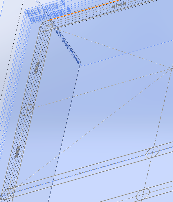
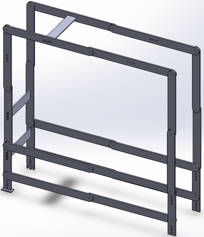
Here’s the finished model - or at least as finished of a model I’ll need to make all of the parts. Note that all joints have two arms in different parallel planes, and the beams joining the front and rear frames are of different length. Several of these beams are not shown in the model, but it contains one of each different length, which is the important part.
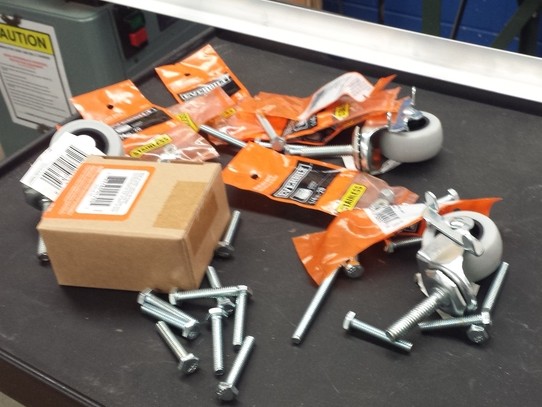
Next up is a trip to Home Depot to get all of the hardware to assemble this. The list includes:
- One 36” aluminum angle bracket, to be cut into 10 pieces
- 18 1-1/2” long 1/4-20 hex bolts
- 4 2-1/2” long 1/4-20 hex bolts
- 22 1/4-20 nylon lock nuts
- One box of 100 1/4” fender washers
- 4 non-marking swivel casters
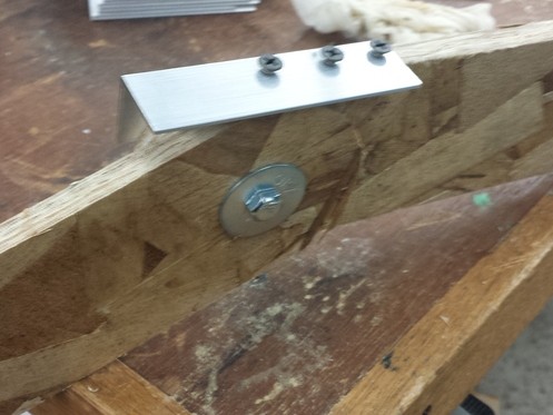
The angle brackets are screwed on to certain joints so that they can lock into a straight position when the structure is fully unfolded. The nylon lock nuts secure each bolt, with washers between all pieces and at both ends. The nut is tightened just enough so that the joint is pretty stiff but can still rotate. The washers along the bolt prevent two pieces of wood from directly touching, possibly seizing the joint and ripping off the surface of the OSB. Overall, wood-on-zinc-washer seems to be a pretty good improvised thrust bearing.
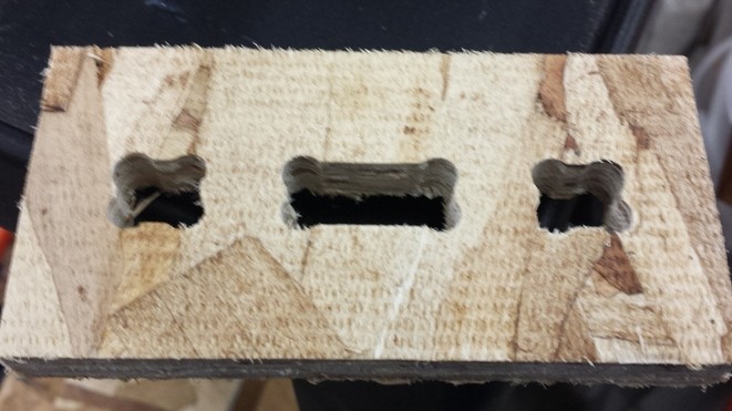
On many sharp angles, I added dog-bone fillets using the VCarve software, which cuts out the corner using the end mill and makes tight mates possible. Note the final cut shape of the female joint compared to the block drawing from SolidWorks.
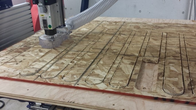
Here’s a picture of the cutting process, which shows two interesting things. First, I was careful to design the toolpaths to cut out all slots, holes, and pockets first before cutting the profile of each part. This ensures that the holes aren’t cut in a random place from the part moving around after losing its support. Second, the ShopBot was using an up-cut end mill, which actually grabbed a piece as it was finishing and ripped the end off. Luckily, OSB is forgiving to the machine and disintegrates easily. Plywood might have broken the end mill here.
A note on end mills: down-cut end mills seem to be strictly superior for this week’s assignment, as they give a smoother top finish (and also a decent bottom finish as long as the part is clamped down) while up-cut end mills make very ragged edges that need to be filed down later. Moreover, they also help to hold down the part while cutting. The improved chip clearing of the up-cut doesn’t seem to matter much when there is a huge vacuum attached. However, all of our down-cut end mills this week have been broken, including one by yours truly when I tried to make an air cut at the wrong height (Sorry!)
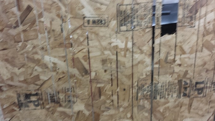
The following is what happens when one doesn’t cut all the way through the part. I even restarted the job to cut deeper, but apparently not enough. I had to spend a significant amount of time extracting these parts and filing down rough edges afterward - much longer than the cutting process itself took. On the upside, these turned out to be unexpected tabs that helped to hold parts in place during cutting.
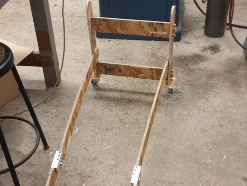
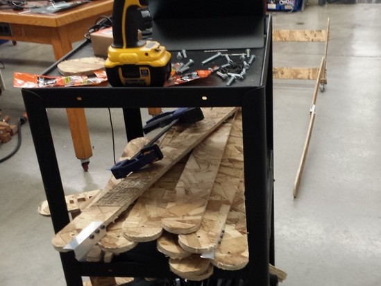
I’ve started with the assembly of the bottom part of the net. Note the press-fit mating joints, and the caster wheels screwed in to an appropriate size hole and held in place by the rectangular feet.
There are 36 different parts to this structure. That’s a lot of filing, cleanup, and assembly. I’ve been in the shop almost 12 hours at this point, mostly because the machine was tied up all day.
After much blood, sweat, and tears, success! At least the structure can be assembled into its unfolded shape, so that it can serve its intended purpose - at least, after I obtain a large net to attach to the frame. There are a few extra undesirable degrees of freedom here, because it’s essentially a large parallelogram - but nothing that can’t be remedied with some cleverly placed staples and straps to limit joint angles.
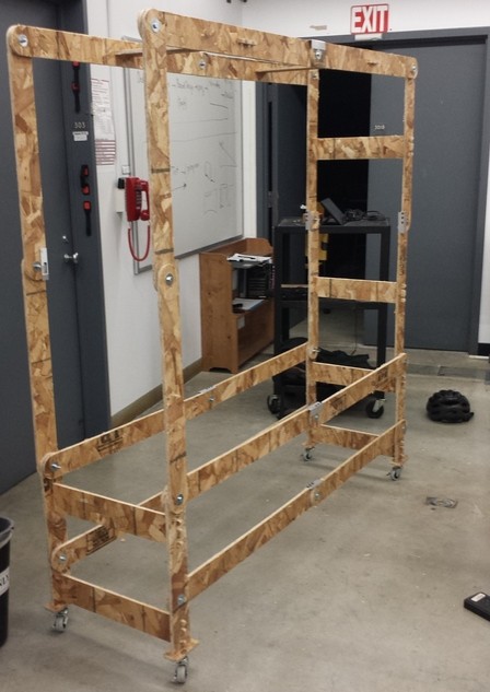
The asymmetry between the two sides is intentional - one has beams because it folds inside of the other arms, and the other doesn’t because it folds outside. I added as much structural support as possible without compromising the ability to fold it up.
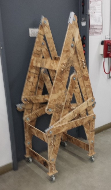
This is the real moment of truth - whether it can fold up in the two axes as intended. After some additional grunting, I found that it wasn’t too hard to fold the net into its collapsed shape, which is both narrower and shorter than the original structure. And it still rolls around on all four wheels!
I may have bitten off a bit more than I could chew this week, as even
TA David Robert said that my structure was “epically big” when he saw
it. What?, I asked? I thought we were supposed to be making
something big. Turns out I completely underestimated the amount of
time I would need to spend in the shop getting everything cut and
assembled - but all’s well that ends well!