Weeks 9-10: DC Motor Controller
Overview
For my final project, I’ll be making an electric go-kart or other vehicle, and one of the important aspects of this will be the motor controller, which allows for varying the amount of power sent to the motor. Motors for electric vehicles can be broken down into three main categories:
- brushed permanent magnet, which is self-commutated and turns as long as a voltage is applied
- brushless permanent magnet, requiring an external electric commutator
- electrically excited, where the magnetic field is generated by the power source, and can be commutated by different means of DC or AC control
The latter two categories of motors were not really possible to use electric vehicles until the advent of microcontrollers and power electronics. However, I’ll mainly be working with the brushed permanent magnet motor here, which are very common in small to medium sizes and with which I’m more familiar.
Because a motor can draw a lot of power and is electrically noisy, it must be separated from the logic electronics. The general idea is to use MOSFETs to turn the motor on and off, with PWM to control its speed. The ideal configuration for driving a motor (or other inductive loads) is an H-bridge, which contains four switches that can be simultaneously controlled so as to apply voltages with PWM to the motor in both directions. However, in reading about power electronics for the last two weeks, I quickly realized that the class parts are not ideal for building an efficient H-bridge, for several reasons including the following:
-
All efficient designs use N-channel MOSFETs instead of P-channel, because they have a third of the RDSON (drain to source on resistance), being majority carriers. To drive an N-MOSFET on the high side requires a charge pump, which requires a floating midpoint voltage reference and can increase the voltage above the positive power rail.
-
All of our parts are logic-level MOSFETs instead of “normal ones”, meaning they switch at lower voltages but suffer from slower switching time, gate capacitance, and on-resistance.
-
All MOSFETs have a gate capacitor which is charged to start conducting and discharged to stop. This capacitor must be charged and discharged as quickly as possible, otherwise the MOSFET is in a semi-conducting state which dumps a lot of heat. Although the logic-level MOSFETs can be switched directly by the IC, they will be switched slowly by the limited current the IC can provide and this is further compounded by the issues above. Most of them are solved by using a gate driver IC, which includes the charge pump for the high-side FETs and also can charge and discharge the gate capacitor at much higher currents. These are not included in the class parts.
-
For freewheeling diodes and other rectifying devices, we need high power Schottky diodes that drop low voltage and can handle a lot of power. The biggest diode available in the class is a 100V/1A Schottky, which is going to be easily blown by the 16A that can be switched by the TO-252 N-channel MOSFET.
-
Fairly large electrolytic capacitors are needed to smooth out the inductive voltage spikes in switching high loads. There aren’t any of these in the class, and furthermore they are going to be through-hole components which will complicate fabrication somewhat.
Here are several good resources I’ve found for topics on power electronics, if you also get interested in this topic like me and want to investigate further:
-
Charles Z. Guan’s Blog: Charles has figured all this out from designing his own motor controllers, and put together a power electronics tutorial in response to our collective request for help.
-
H-Bridge Secrets: A website where you can find out more than you ever wanted to know about H-bridges.
-
MIT 6.131: The class where you’re supposed to actually learn this stuff properly.
-
Power MOSFET, charge pump, gate driver, and freewheel diode on Wikipedia.
Design and Fabrication
So if we can’t build an H-bridge with the parts provided in the class, what can we build? Well, I’m going to start with the jankiest type of motor controller possible, a low-side driver. By the end of the semester, I may be able to move on to a slightly better design using a half-bridge.
The low-side drive basically uses a single N-channel MOSFET with the source hooked to ground to turn the load on and off. Because the motor is an inductor, it needs somewhere for the current to flow during the off portion. This is accomplished with a Schottky freewheel diode, which is quick to turn on and drops a low voltage. During the off portion of the duty cycle, the diode and the motor windings dissipate energy as heat. The fast switching time of the diode is needed to match the PWM switching speed, and the low voltage drop reduces the amount of heat that must be dissipated.
Here’s a diagram of the initial board I designed, using the information I was able to scrape off the Internet:
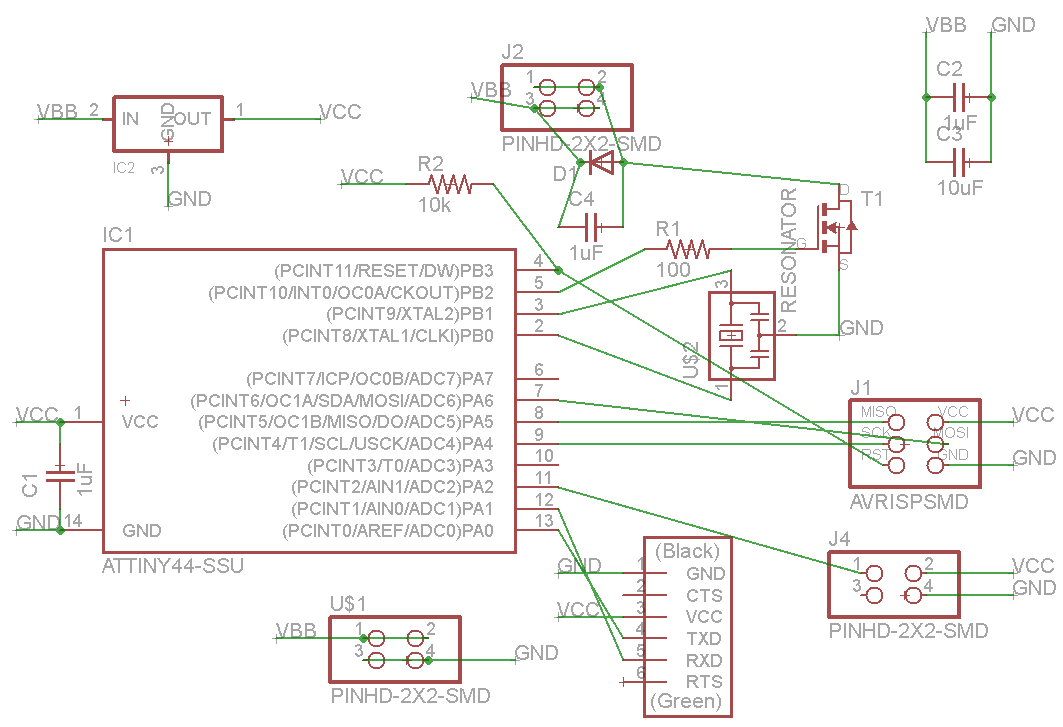
Note the following features:
- Bypass capacitors all over the place, including across the power rails, the motor, and regulated voltage. Batteries and motors create all sorts of noise that must be filtered out, or they can do weird things to the microcontroller. I don’t know what the “right” values are for these, but more can’t hurt.
- Gate resistor between the IC and the MOSFET. I’m going to be using the beefiest MOSFET provided in the class, the RFD16N05LSM, so hooking it up to the microcontroller directly may draw too much current.
- Freewheel diode connected in antiparallel across the load
- Multiple headers: power, load, programming, FTDI for debugging, and sensor.
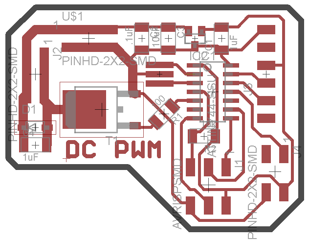
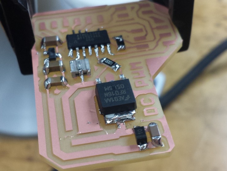
This is what the board looks like once it’s all laid out. Charles confirmed my intuition that the power traces should be kept on one side of the board and be as short as possible. You’ll also want to avoid large loops from traces that are trasnsmitting a lot of power. This is my first design, so no doubt it’s going to have some interesting quirks, to say the least. One thing that is definitely bad about the design below are the two logic grounds that are connected in different places to the power ground. Instead, the logic ground should only connect to the power ground in once place and generally be as far away as possible. This is pretty much guaranteed to cause some strange behavior - one phenomenon I observed in particular is very noisy readings from the sensor with the motor on.
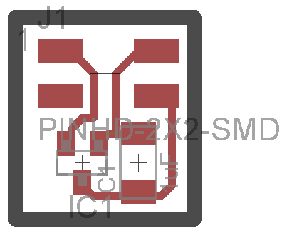
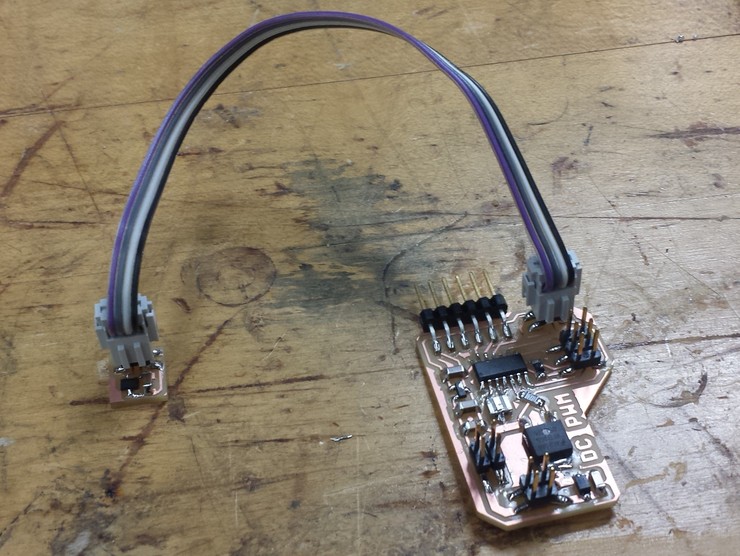
On a separate board, I’ve put a Hall effect sensor with a header to connect it back to to the main board. This sensor is separate so that it can be used for a non-mechanical throttle that may not be physically on the motor controller itself. Potentiometers were common for old throttles, but the Hall effect sensor is now preferred for most applications because there is no physical component to break or wear out. It’s used widely as a standard in electric scooters, and is generally safe - a magnet needs to get within centimeters of the throttle before it can affect the reading significantly.
Below, I’m soldering the power MOSFET to the board. The drain actually has a large metal area that is designed to help with heat conduction. In order to maximize the contact the board, I’ve first tinned the entire pad area.
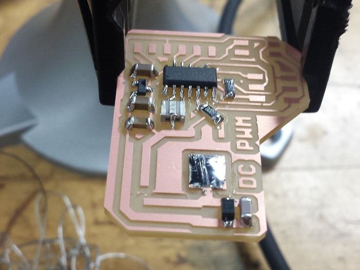
Next, I pushed down on the MOSFET while simultaneously heating up the drain with the soldering iron. Once hot enough, the entire component lies down flat on the pad. In my case, some solder spurted out of the side, which had to be cleaned up.
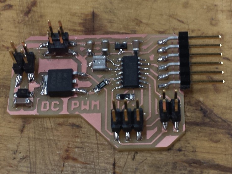
Here’s the entire board. From left to right, the headers are:
- load, which the motor is connected to
- power, for the battery or other power source.
- programming header
- sensor header, for the Hall effect sensor on the daughterboard
- FTDI header for debugging.
Both the power and load are connected to the 0.05” extra thick traces, isolated to the left of the board.
This is the idea behind the “motherboard” and the sensor “daughterboard”. I have the sensor on a short cable for now, but it can be extended later to whereever the throttle needs to be.
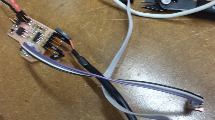
The main reason I added the FTDI connector was to be able to debug the board as I was programming it. However, the board is designed to be powered off an external supply that is then passed through the regulator. Hooking up power through the FTDI cable alone caused the regulator to heat up uncontrollably, probably because it is not meant to be operated in this way. However, I discovered it was possible to read signals from the board using just the ground, TX, and RX pins of the FTDI cable, as it was being powered from the supply.
I later confirmed that this is the right way to use the FTDI cable to talk to a powered board.
Magnetic Sensor
The first part is to just adapt the Hall effect sensor code from the ATTiny45 to the ATTiny44, and verify that it works. The following is the magnetic sensor code adapted to set up the ADC on port PA2 of my ATTiny44:
ADMUX = (0 << REFS1) | (0 << REFS0) // Vcc ref
   | (0 << ADLAR) // right adjust
   | (0 << MUX3) | (0 << MUX2) | (1 << MUX1) | (0 << MUX0); // ADC2
ADCSRA = (1 << ADEN) // enable
   | (1 << ADPS2) | (1 << ADPS1) | (1 << ADPS0); // prescaler /128
Note that the voltage from the sensor is converted to a 10-bit value, so it reads from 0 to 1023, with ~512 being a neutral reading. It was extremely surprising to me that this part just worked without any hitches - everything from the headers to the daughterboard.
To adapt this 10-bit number to a PWM speed, I clamped it to a range: anything below 520 is off, and anything above (520 + 255) is full speed. Thus, the sensor operates with one pole of a magnet, is off at default, and can be turned fully on once the magnet gets reasonably close. The rare earth magnets provided in the class can easily activate the sensor over its entire range, but the reading is highly nonlinear at close distances.
As in Neil’s example, I take several ADC readings before computing an average, and use this value to determine the PWM speed. It helps to use a number of readings that is a power of 2 to do quick integer division using bit shifting:
// ... in headers
#define samplebits 6
#define nsamples 1 << 6 // number of samples to accumulate

   // ... inside main loop

   while(1) {
      accum = 0;
      for (count = 0; count < nsamples; ++count) {
         //
         // initiate conversion
         //
         ADCSRA |= (1 << ADSC);
         //
         // wait for completion
         //
         while (ADCSRA & (1 << ADSC));
         //
         // add result
         //
         accum += ADC;
      }

      // Set new PWM value (range 0 to 1023)
      // 512 is neutral, but we need some buffer room on the low end.
      int speed = (accum >> samplebits) - 520;
      // Truncate higher values to 255 because max reading requires strong magnet.
      if (speed < 0) speed = 0;
      OCR0A = (speed > 0xFF) ? 0xFF : speed;
   }
Driving a Motor with PWM
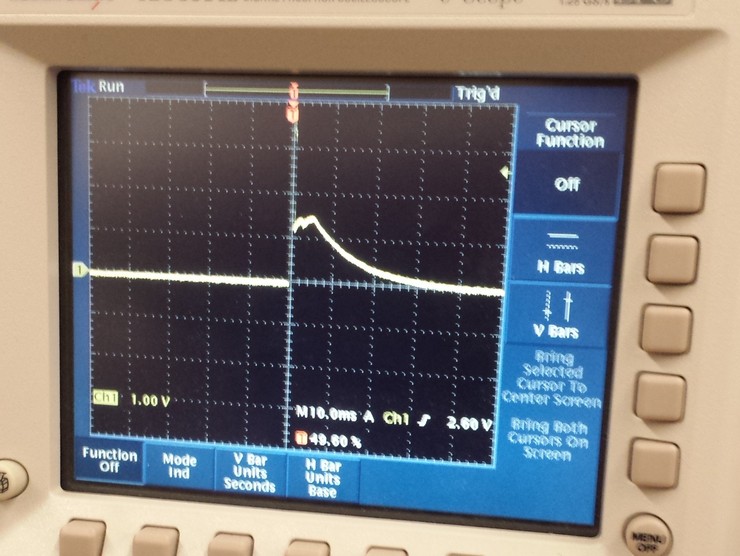
Next, I just tried turning the MOSFET on and off for long (~1000ms) intervals. I had a somewhat large 12V motor connnected that was capable of drawing over 1A of continuous current. However, the motor was just twitching instead of fully turning on. The oscilloscope showed the following pattern for the load voltage. Note that the MOSFET basically turned off after only 5ms or so, and never reached the full on state.
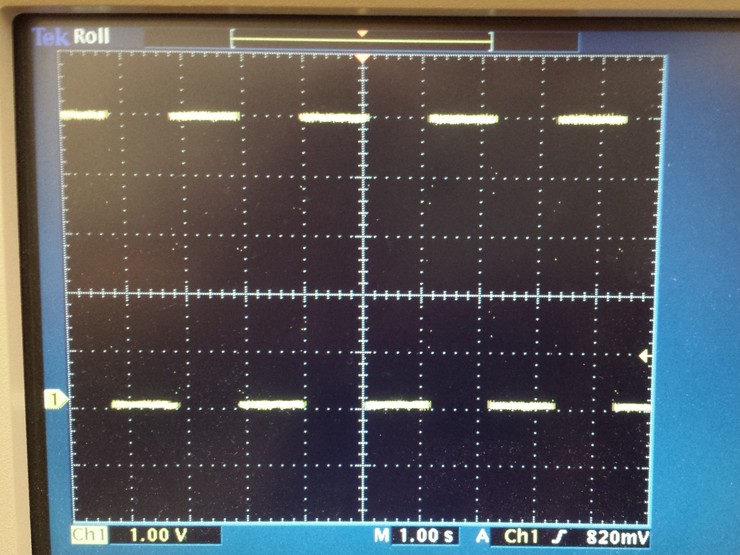
This quandary would take several more hours to debug. First, I noticed that removing the motor caused the expected voltage on the load pins (the power supply was set to 10 volts):
However, adding the motor to this caused a very strange pattern to appear, where the 1 second period was quickly replaced by a series of brief pulses - definitely not corresponding to the 1 second intervals with which I was turning the motor on and off.
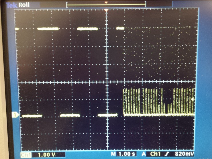
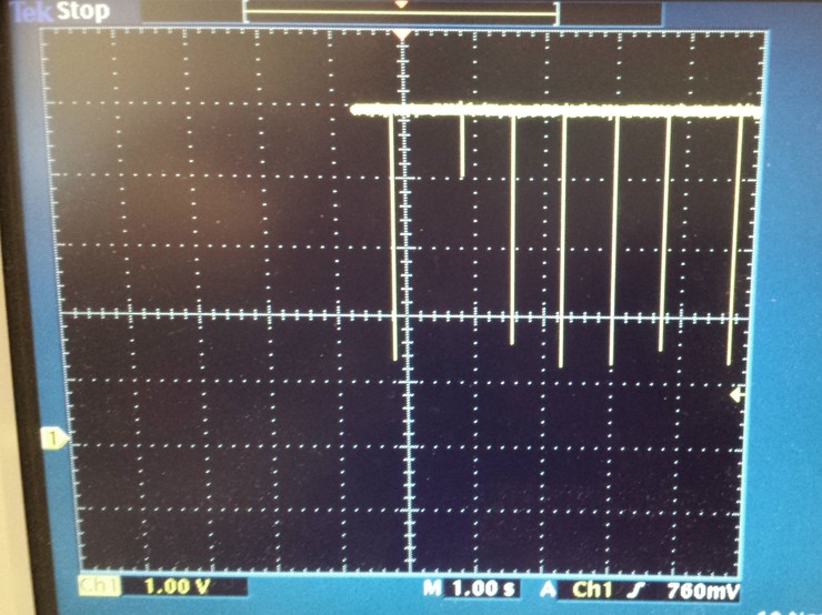
It took me a while to figure out that the motor was actually interfering with the microcontroller and causing it to restart. This is confirmed by hooking up the oscilloscope to the regulated voltage, and noticing that it basically drops whenever the motor is starting. This results in resetting the microcontroller, which discharges the gate capacitor of the MOSFET and immediately turns it off after it tries to turn on.
Because motors can draw high transient currents when starting, this could have been the result of one of several issues:
- A lack of an electrolytic capacitor to produce extra power during start-up
- An insufficient size regulator to power the microcontroller for gate charging
- The current limit on the linear power supply being set too low
Upon reflection, the last point was probably what caused this issue: the current limit just kicked in during startup and turned everything off. However, I also switched to a smaller motor and increased the gate resistor to 250 Ohms, just in case.
I have the gate of the MOSFET hooked up to OC0A on the ATTiny44,
which uses the 8-bit counter. The following code sets up phase correct
PWM in non-inverted mode. Note that the timer cycle length and
prescaler can be used to compute the PWM frequency.
// Initialize motor PWM
// set OC0A on compare match and set non-inverted, phase correct PWM mode, 0xFF TOP
// WGM02 goes in TCCR0B but is set to 0 anyway.
// See page 76 of datasheet.
TCCR0A = ((1 << COM0A1) | (0 << COM0A0) | (0 << WGM01) | (1 << WGM00));
// CPU 20.0 MHz, phase correct PWM (/ 512) is 40 kHz
// Prescaler = 8 will give 5kHz PWM, = 64 will be 600 Hz
// See page 82 of t44 datasheet.
TCCR0B = ((0 << WGM02) | (0 << CS02) | (1 << CS01) | (0 << CS00));
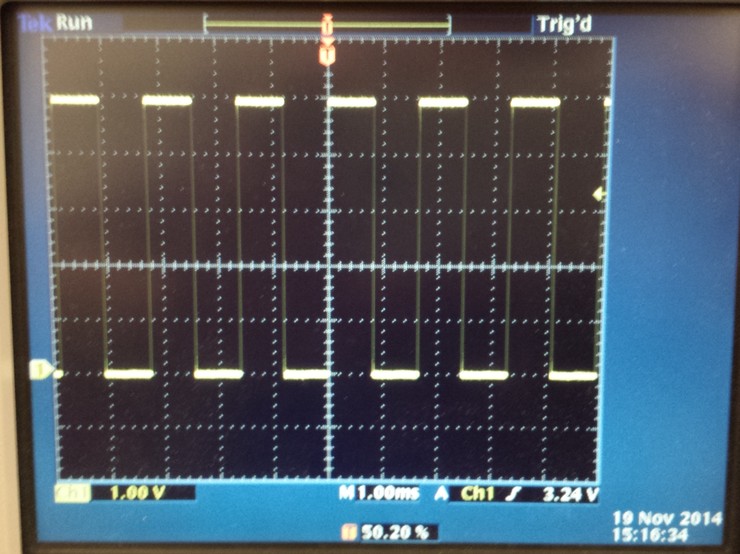
With the prescaler set to 64, we obtain a nice square wave at 600 Hz. This is probably too slow for PWM though, and clearly the gate is able to switch quickly enough here.
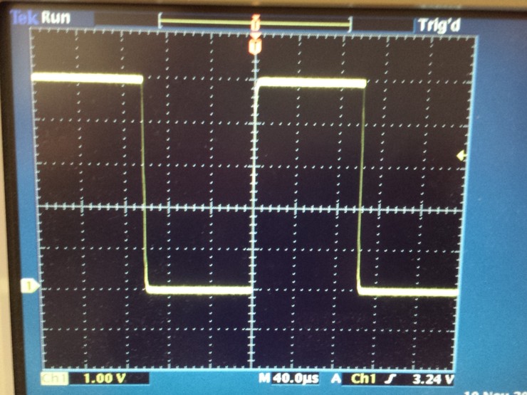
Decreasing the prescaler to 8 yields 5 kHz PWM. Here we can actually see the gate charge and discharge. Each horizontal grid is 40 microseconds, and it seems the gate is turning on and off within a few microseconds. That’s not bad at all, considering the gate resistor is 250 Ohms. We could probably do even better in future desigs.
One of my biggest fears coming in to this project was that the tiny microcontroller wouldn’t be able to drive the gate of the relatively large MOSFET at a reasonable speed. Although 5kHz is in the audible range, this waveform isn’t too bad for most of the things we can do in the class. I’m considering trying to improve the gate drive further for the final project.
With everything working, it’s quite fun to play with the PWM while simultaneously looking at the oscilloscope. Note the spinning motor in the bottom left - although at most PWM speeds, the tape on the shaft is spinning too fast to see.
Future design improvements
Making a very efficient (H-bridge) motor controller is definitely outside the range of this class. However, this was an extremely useful exercise to go through for learning the principles of basic motor controller design, and I really enjoyed this assignment once things were working. Nevertheless, there are several improvements that can be made to this board that are in the scope of the class:
- Better board layout and routing to separate power from logic
- Large electrolytic capacitor across power rails, to buffer starting current
- Bigger regulator (this one got somewhat hot during operation)
- Faster gate drive and PWM speed
- Multiple MOSFETs in parallel to handle bigger loads
- For the freewheel diodes, using either MOSFETs as diodes or larger Schottky ones - these will probably blow out with larger motors
- Half bridge / totem pole configuration
It would be interesting to implement a better version of this for the final project and use it to drive the go-kart, at least out of curiosity. However, the crucial parts I would need to implement this are large (>10A) rectifier diodes and large electrolytic capacitors.