How to Make (Almost) Anything
Project 10
Title: Input Devices
Design: Strain Gauge -> Capacitive Load Sensor
Description:
For the final project, I am planning on making a sensor embedded chair or table that provides interactive structural loading diagram, much like a physical version of finite element model.
I started this week reading about strain gauges and found out that it requires an additional circuit board to interface between sensor and microcontroller. The purpose of this interface board is to amplify the output voltage from strain gauge.
The mechanism of the strain gauge is fairly simple and easy to understand. By gluing it right on the the material whose strain you want to measure, the strain gauge changes its resistance value based on the expansion or contraction of the conductive material.
However, I slowly started to realize that the actual conversion of output signal (voltage) back to quantifiable mechanical value is nontrivial. In comparison to the input voltage, the output voltage from the strain gauge is an order of magnitude smaller. You need to amplify the output signal to be able to measure but it is not easy to amplify the signal without keeping the noise down.
I started contacting our amazing group of TAs.
Will suggested that phidgets provides relatively inexpensive collection of strain gauges.
- Phidgets Strain Gauges:
<1>
- Phidgets Interface Board:
<1>
He also suggested that we can make our own strain gauges by laser etching the strain gauge pattern on flexible circuit substrate.
- Dupont Flexible Circuit Material:
<1>
Jeff suggested me to look into capacitve sensor approach to measure the stress value. This approach is more reliable and scalable. This is indeed the approach suggested by Neil.
Here's some useful links that describes the differences and advantages of capacitive sensing over strain gauge:
- "Capacitive load cells simplify sensing", www.machinedesign.com
<1>
In the meantime, I decided to try out a couple design templates provied by Neil to get myself familialized with the making of embeded sensor objects.
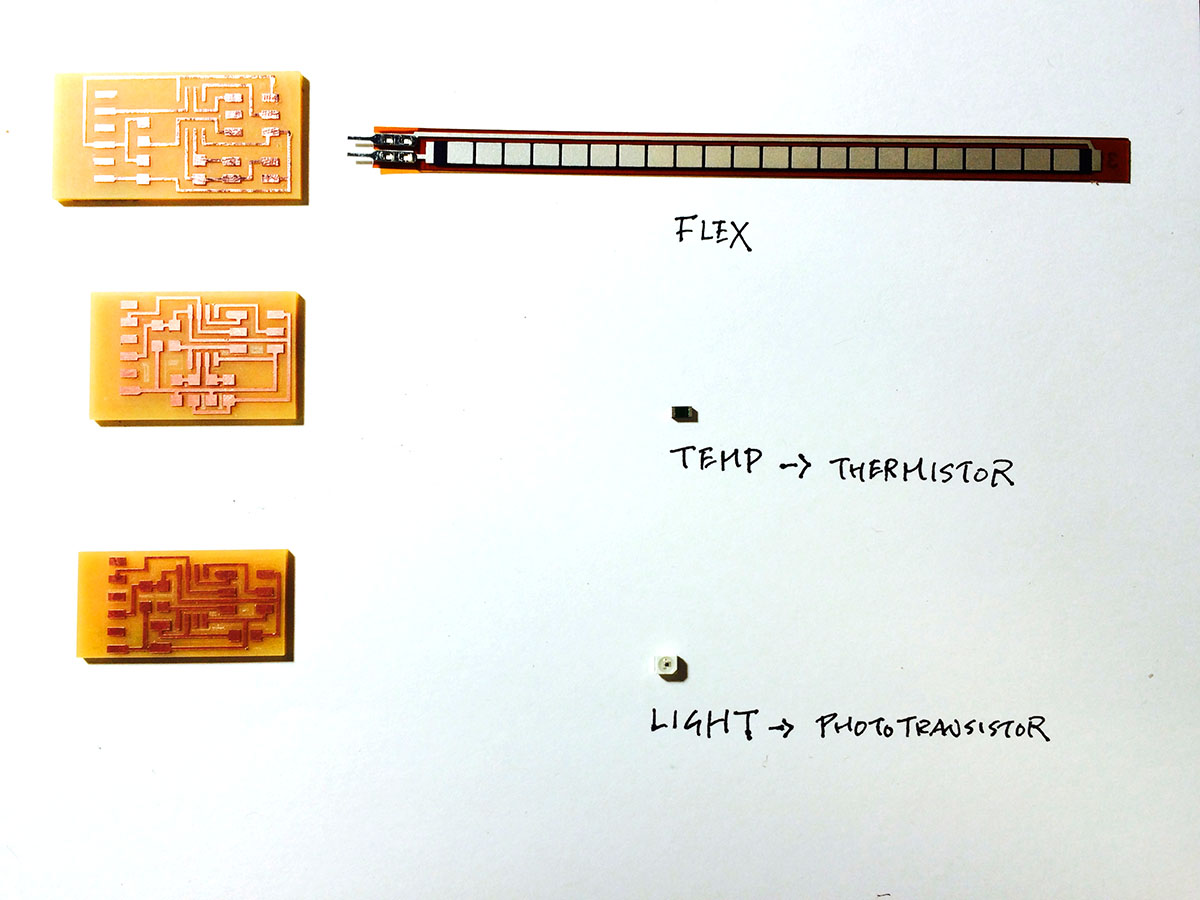
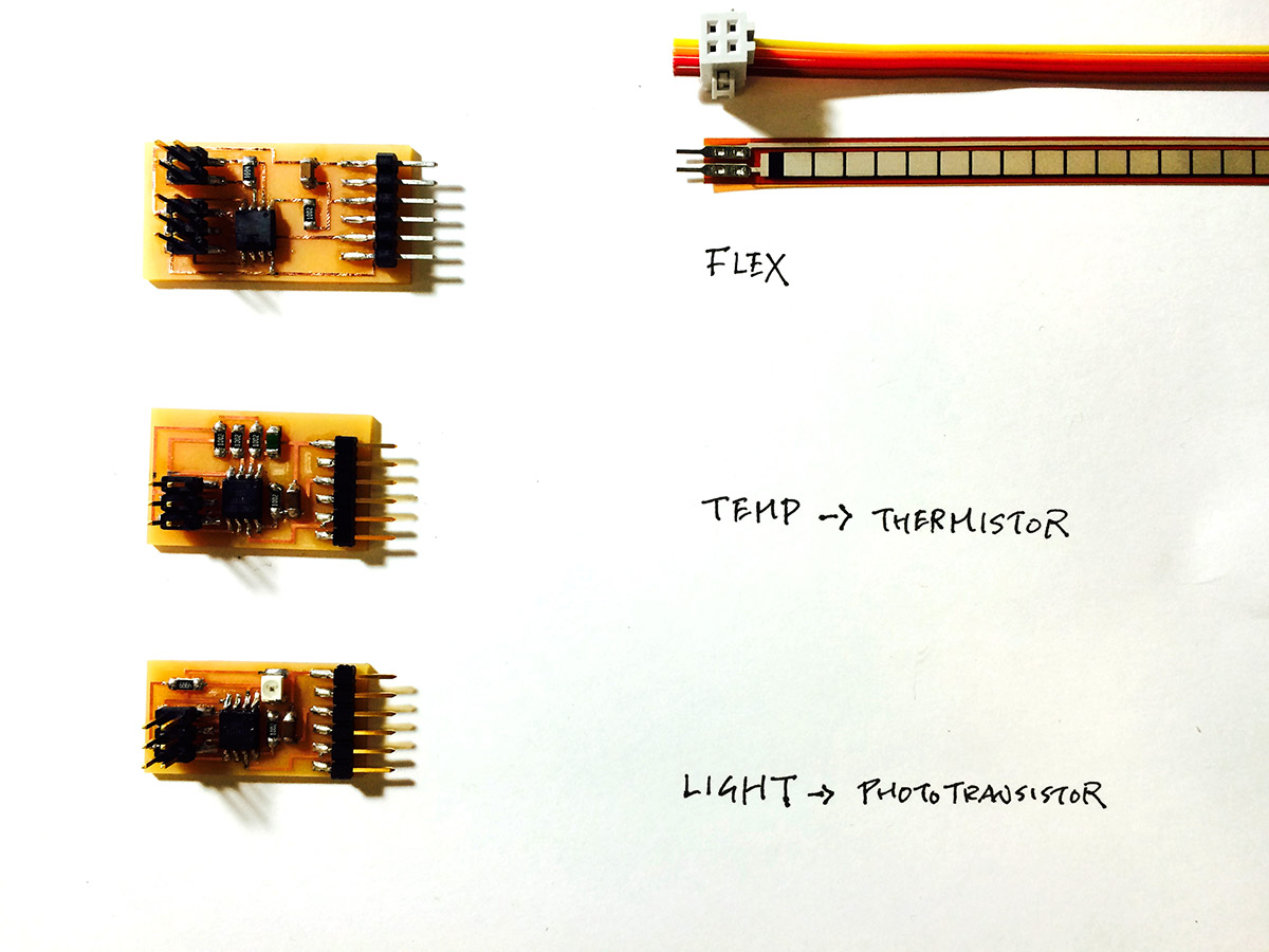
Here's the list of sensors I tried:
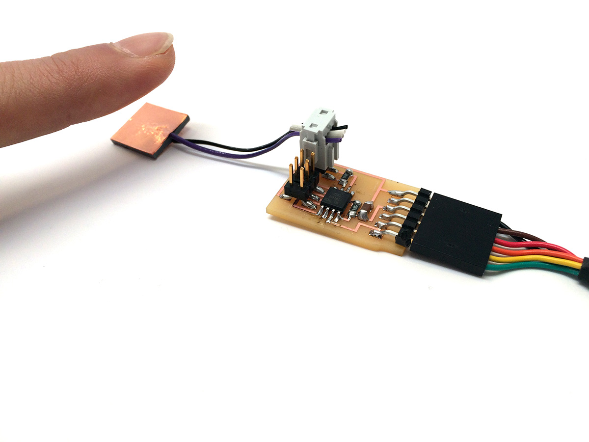
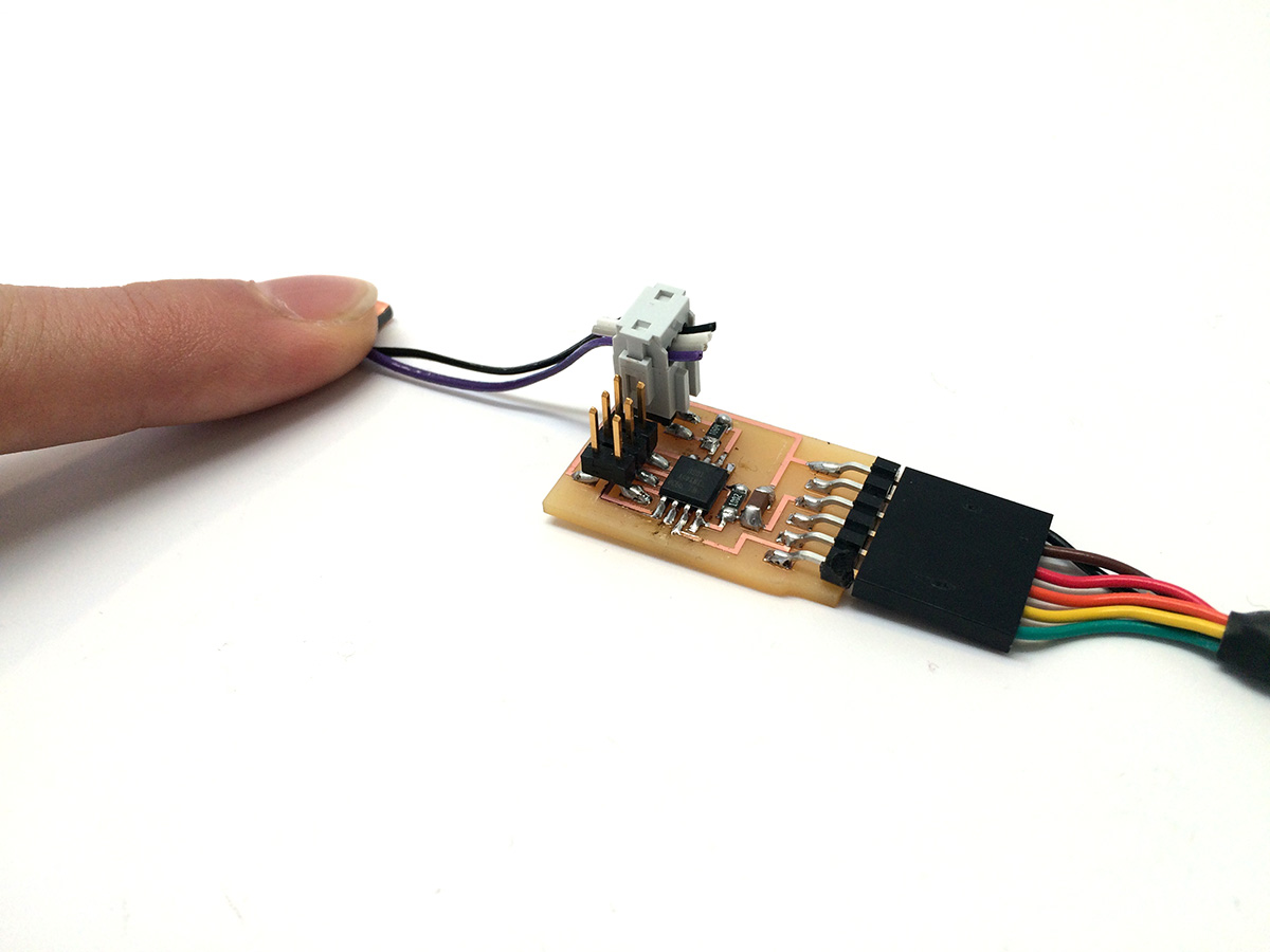
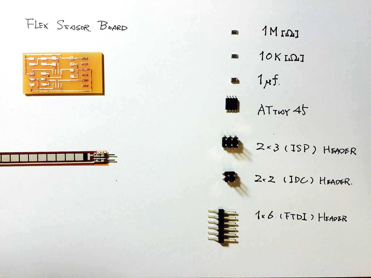
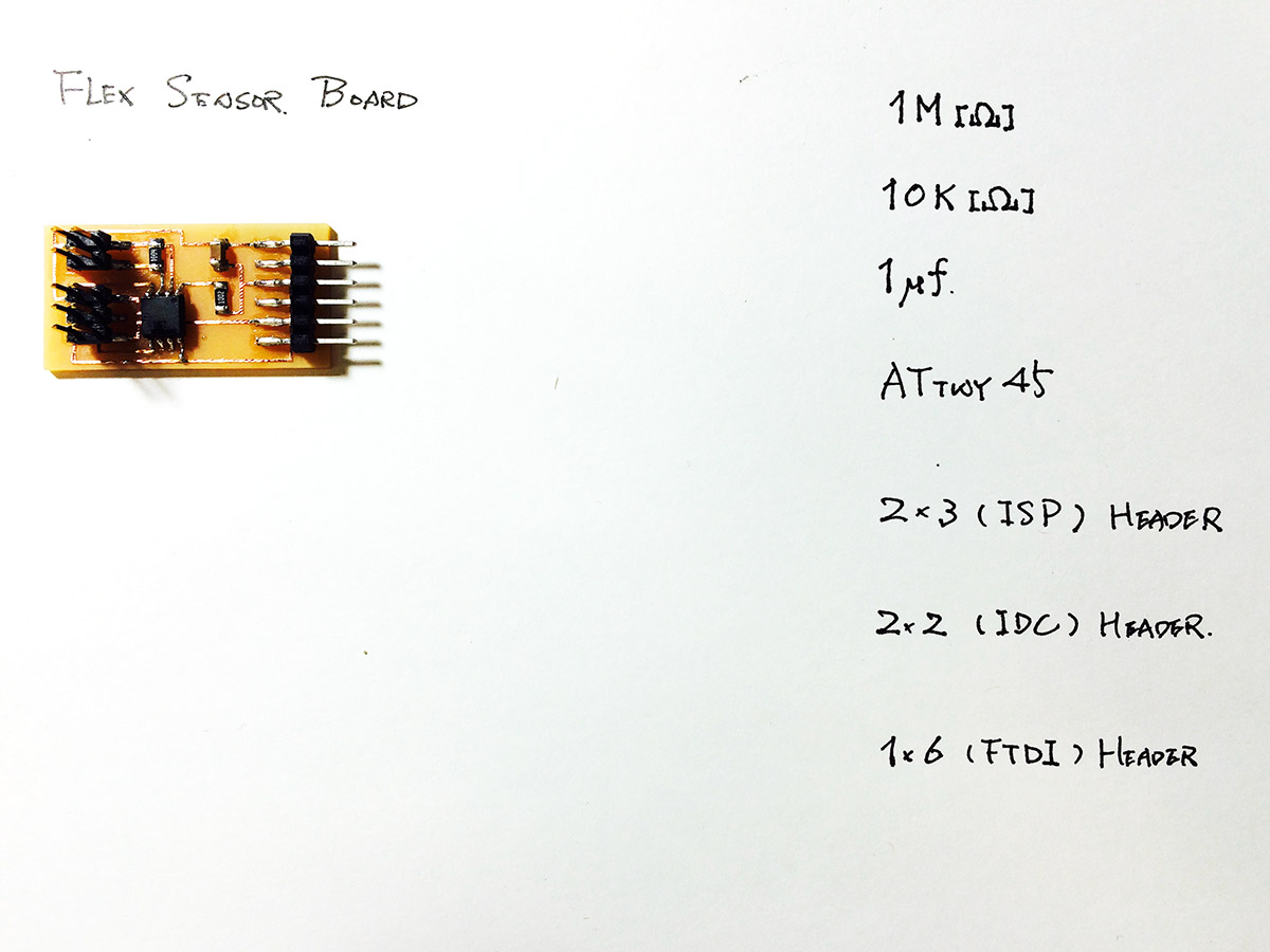
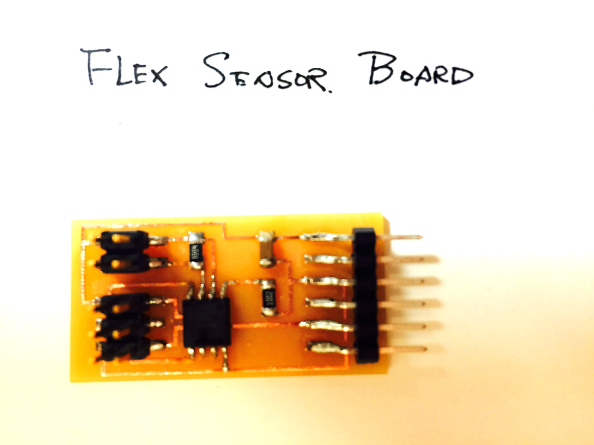
1. Flex Sensor
2. Light Sensor (Phototransistor)
3. Temperature Sensor (Thermistor)
1. Flex Sensor
Data:
- Eagle Scheme<1.1>
- Eagle Board<1.2>
- BOARD<1.3>
- TRACE<1.4>
- BORDER<1.5>
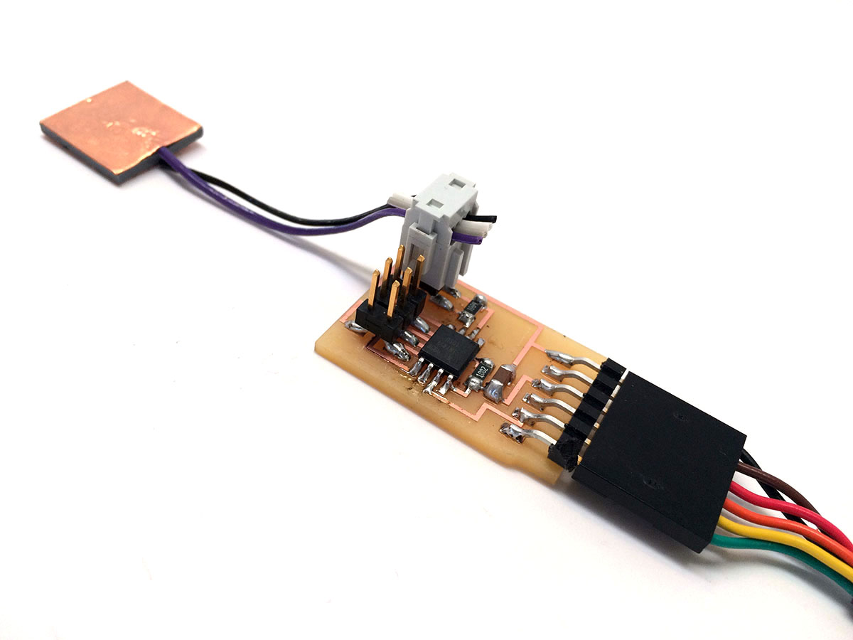
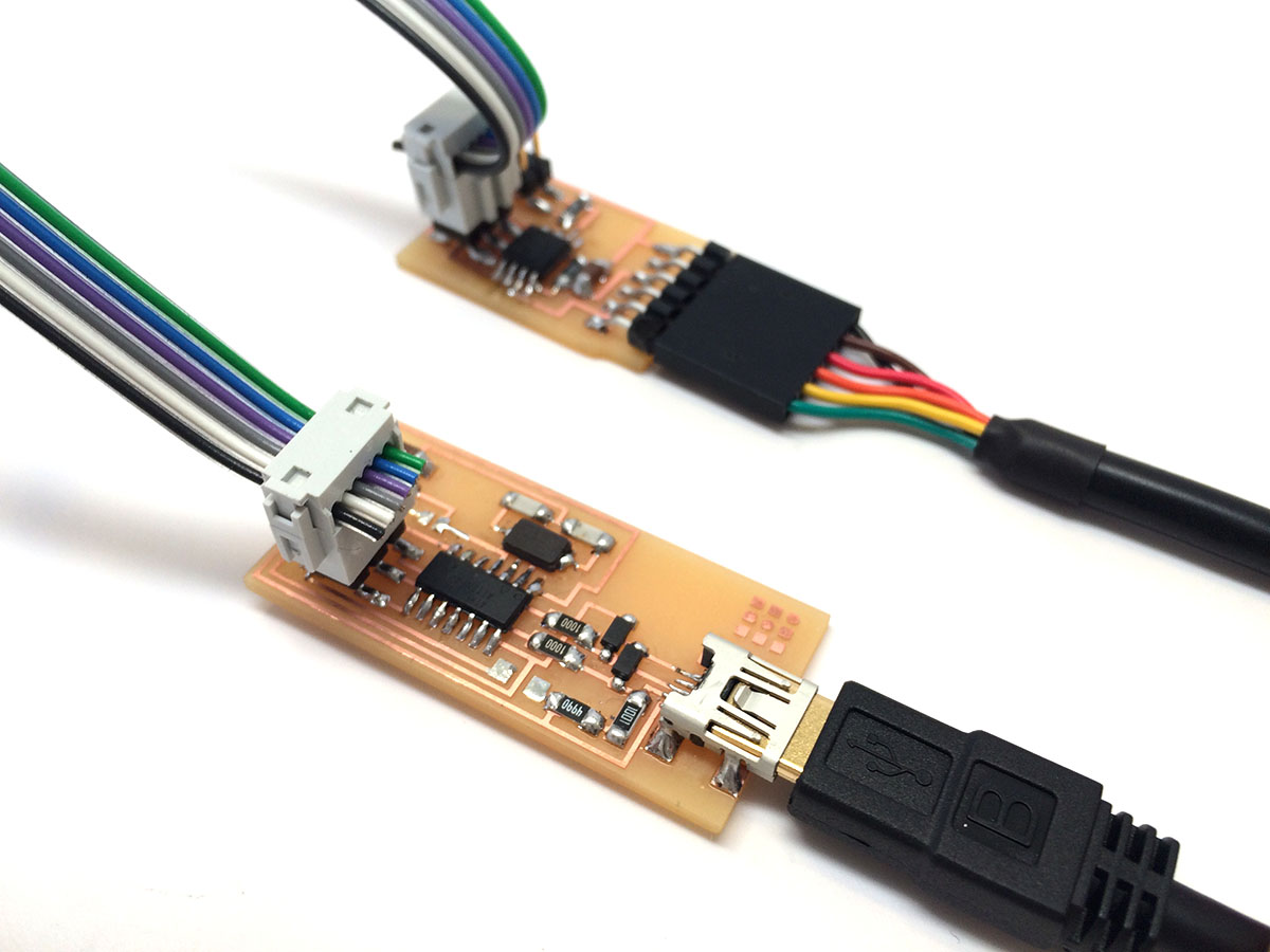
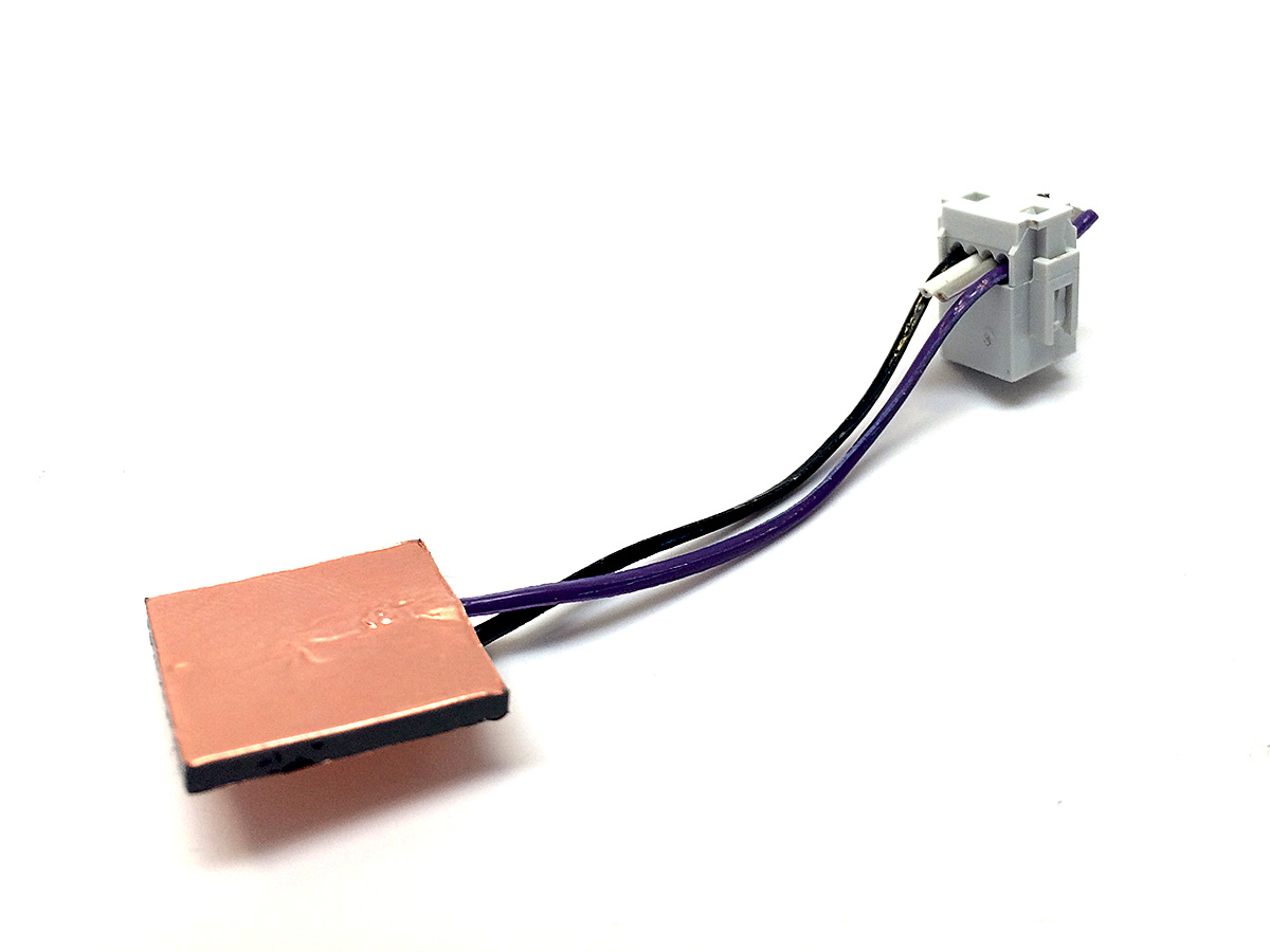
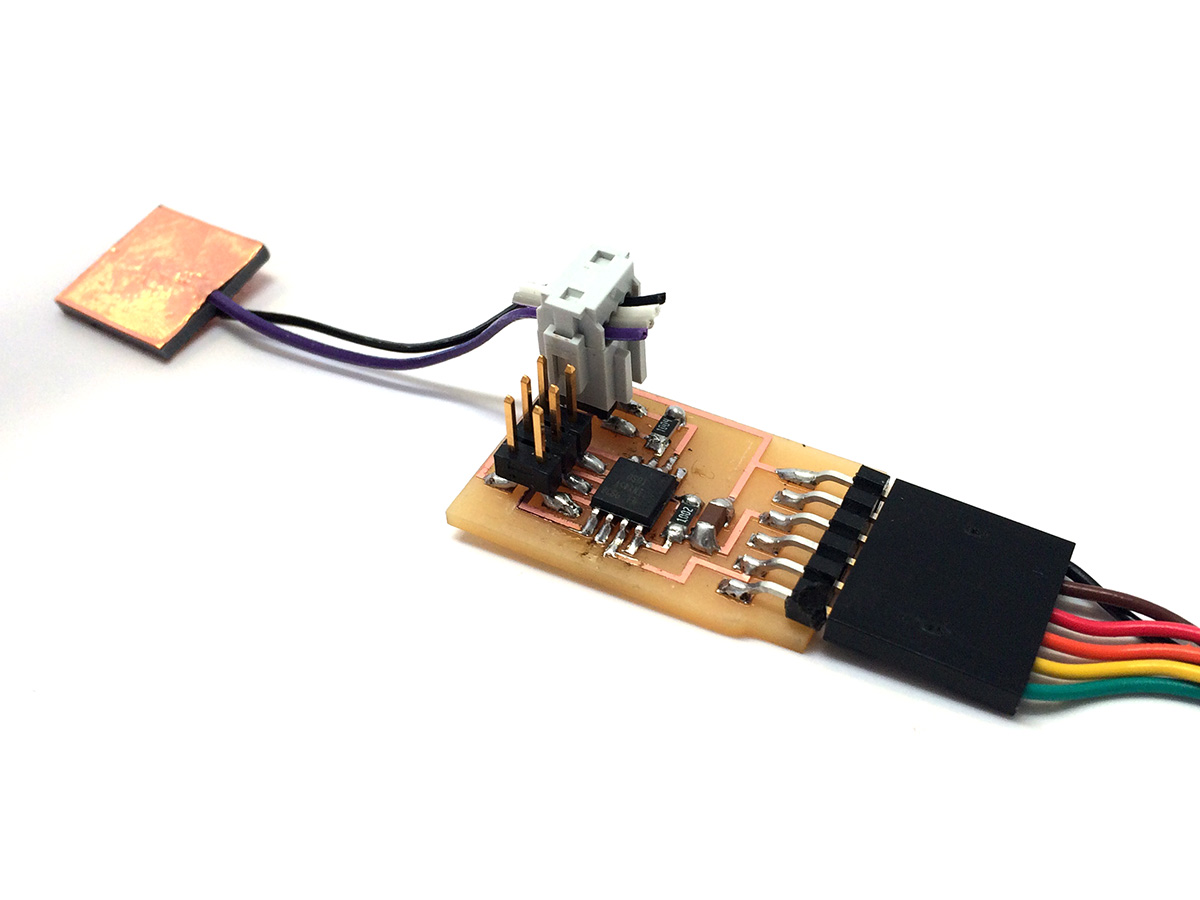
I started with the Neil's template, step response, for measuring change in resistance that is going to happen in the flex sensor. <2>

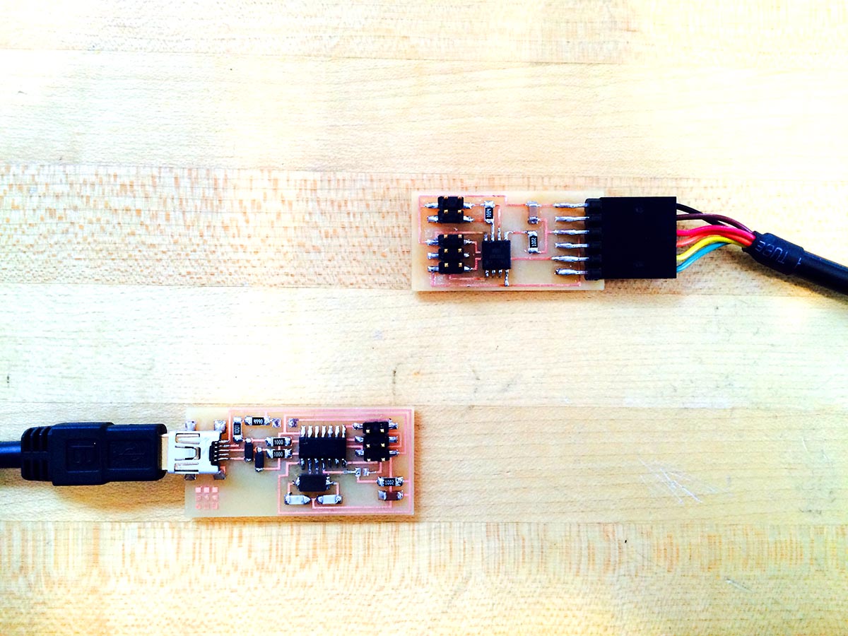
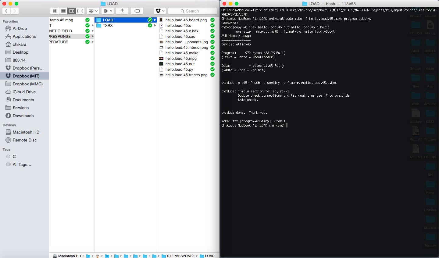
And... it failed to upload the program.
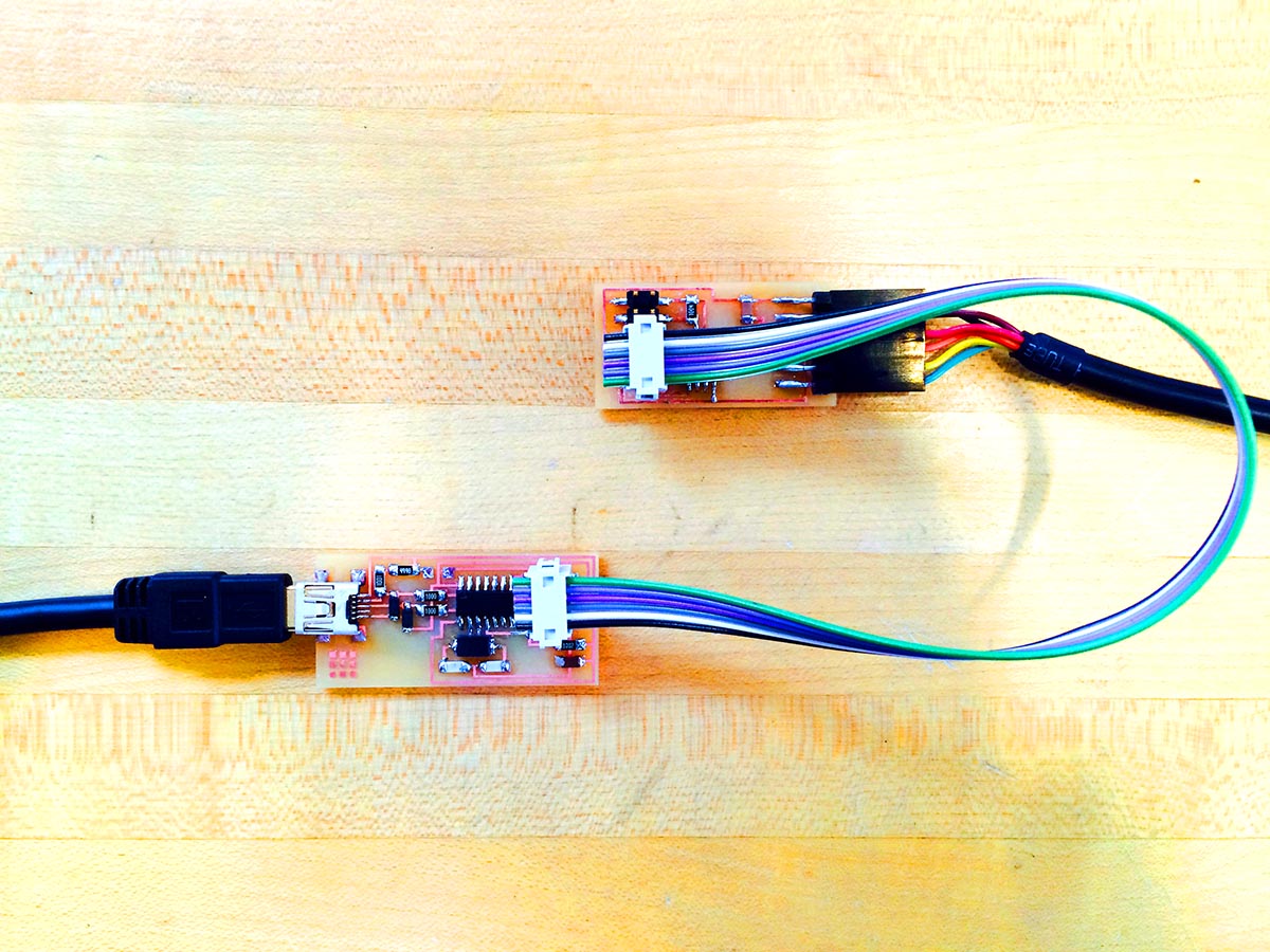
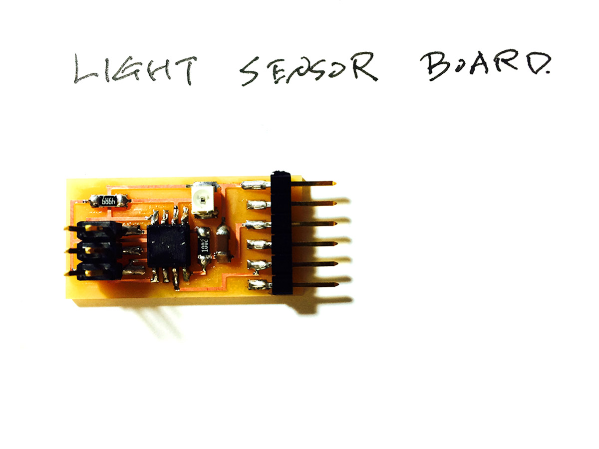
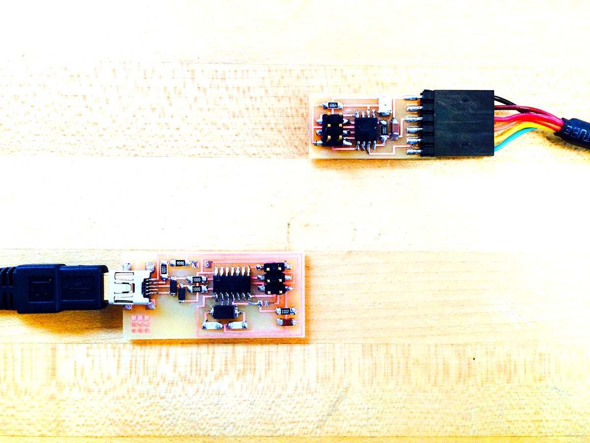
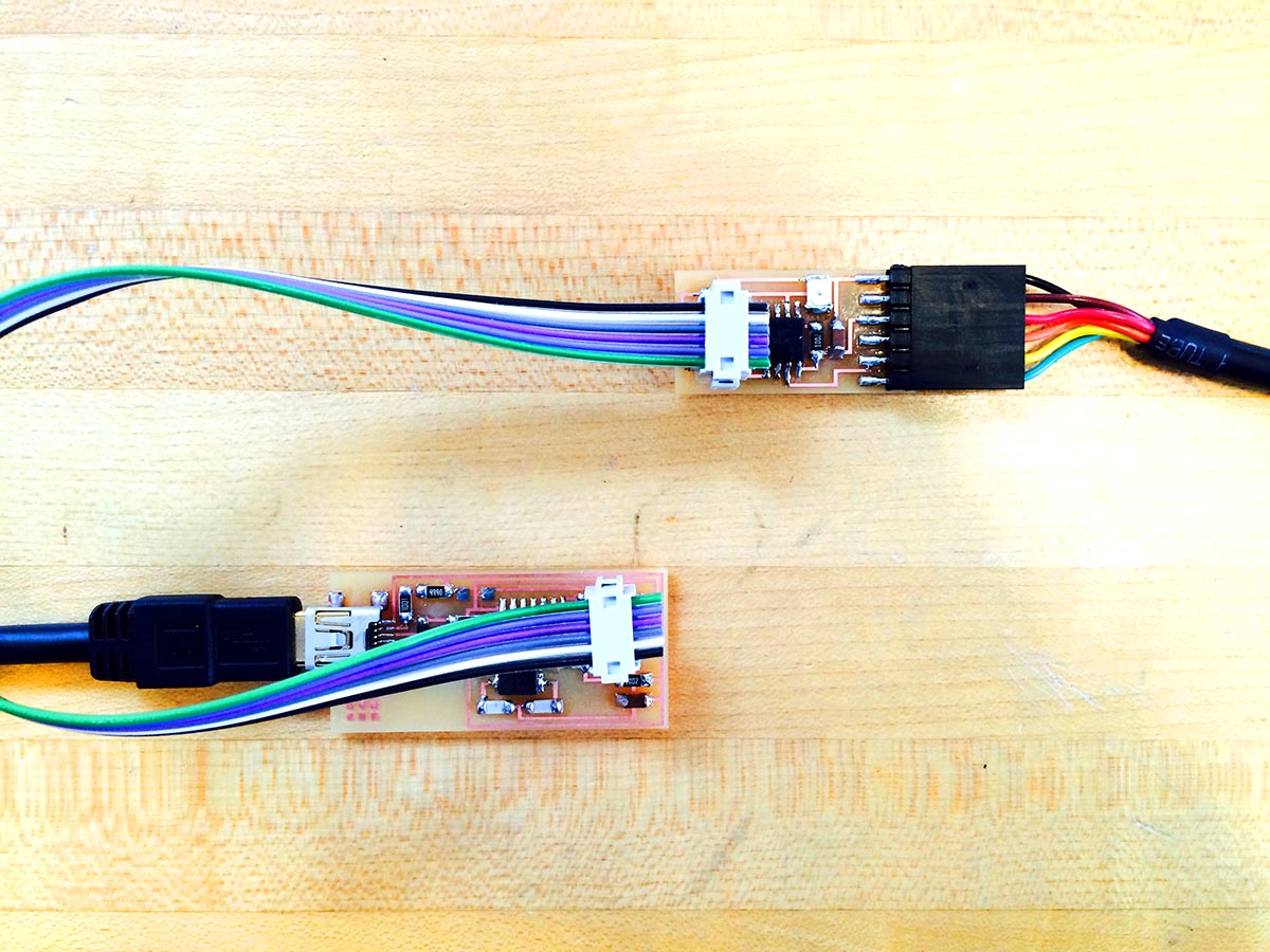
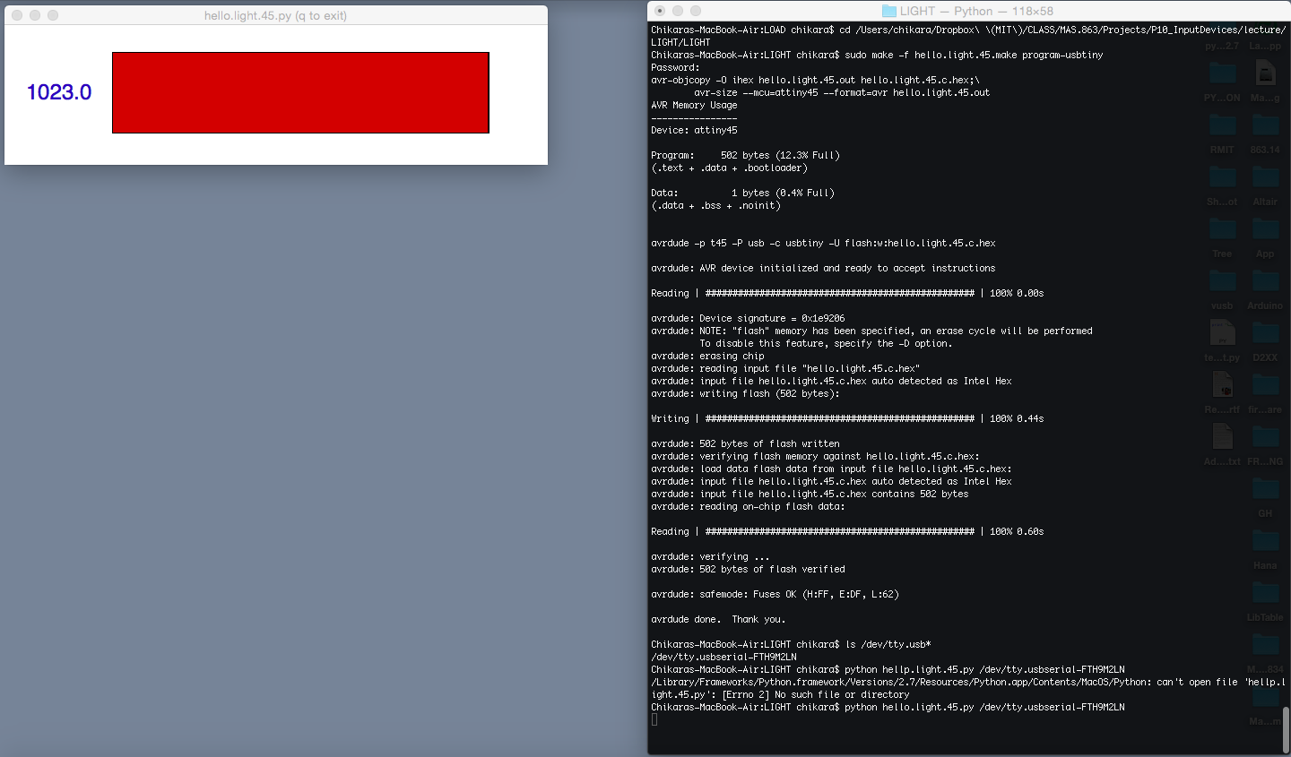
2. Light Sensor
This time the program was successfully loaded; however, the phototransistor was failing to read the change in the light input.
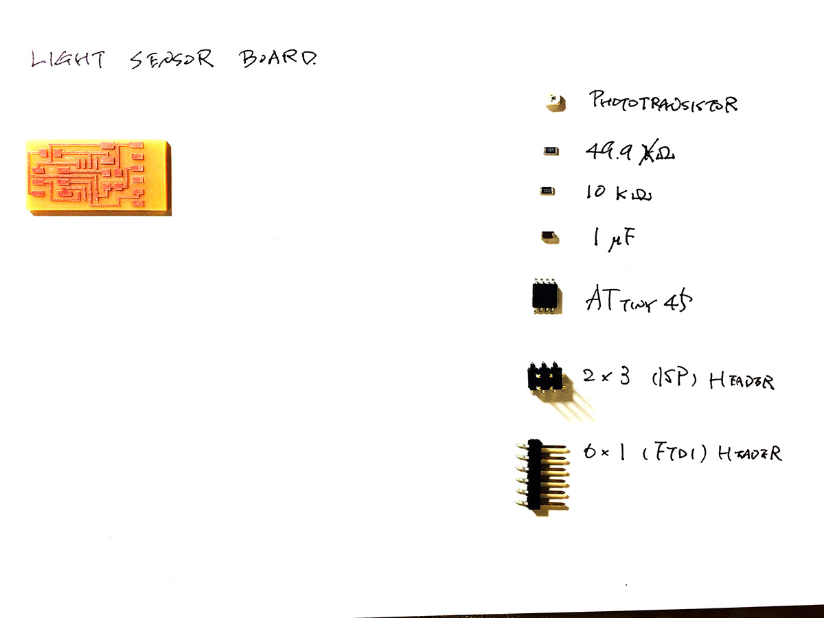
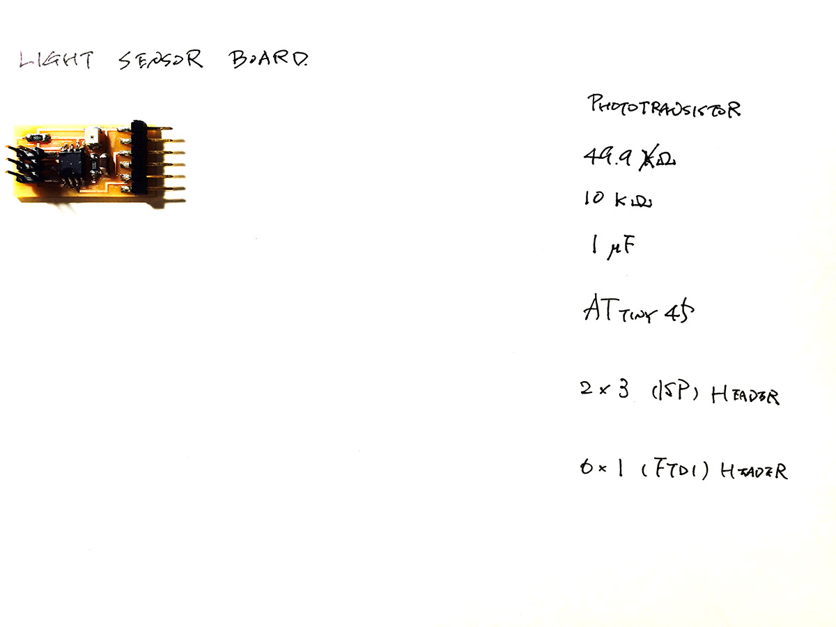
Notes:
Impedance:
The total opposition to alternating current by an electric circuit,
equal to the square root of the sum of the squares of the resistance and reactance of the circuit and usually expressed in ohms. Symbol: Z
Op-amp:
<1>
An operational amplifier is a DC-coupled high-gain electronic voltage amplifier
with a differential input and, usually, a single-ended output.
1. Non-Inverting Amplifier: Vout changes in the same direction as Vin.
2. Inverting Amplifier: Vout chages in an apposite direction to the Vin.
Other Sensors
Strain Gage:
<1>
- is a devise used to measure strain on an object.
- uses the physical property of electrical conductance and
and its dependence on the conductor's geometry.
- increases its electrical resistance when its stretched where the geometry
becomes narrower and longer.
- decreases its electrical resistance when its compressed where the geometry
becomes wider and shorter.
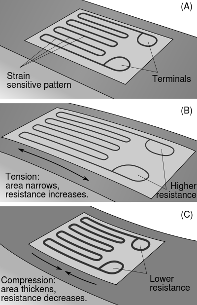
image: http://en.wikipedia.org/wiki/Strain_gauge <1>
Velostat:
<1>
- Velostat, also called linqstat, is a pressure-sensitive conductive material. It reduces the resistance when you apply pressure. It comes in a form of sheet, flexible, and inexpensive; thus makes it a good alternative for off-the-shelf pressure or flex sensors when making flexible sensors for wearable products.
Links:
- Strain Gauge Primer, Phigets <1>- Capacitive Load Cells Simplify Sensing, Mechine Design <1>