back..
electronic fabrication
the fab-isp
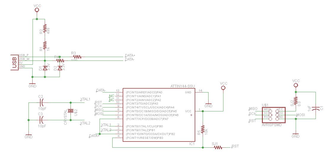
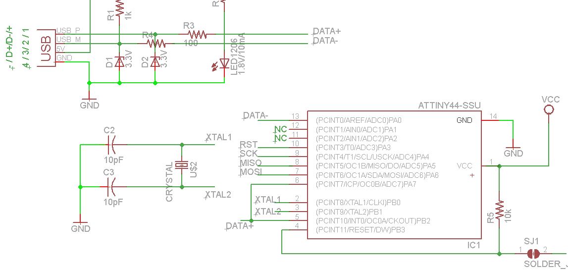
Actually I learned Eagle, the electronic design software used for the schematic representation shown in Figure 1, for the "Electronic Design Assignment". However, I found it useful to at the schematic here, since it gives a good overview of the functionality of the circuit: you can identify the input part (upper left; USB, 5V Input Voltage; 3.3 Volt Zener diodes for voltage stabilization) for the Data-signal), the crystal for timing reference (bottom left), the micro-controller and its input- and output data (middle), as well as the output-circuit (right).
re-designing the fab-isp
In the following you see the same process as above, this time with the ISP-Design from the Electronic Fabrication (week 3) assignment
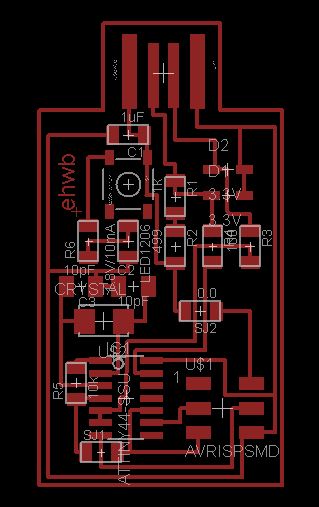
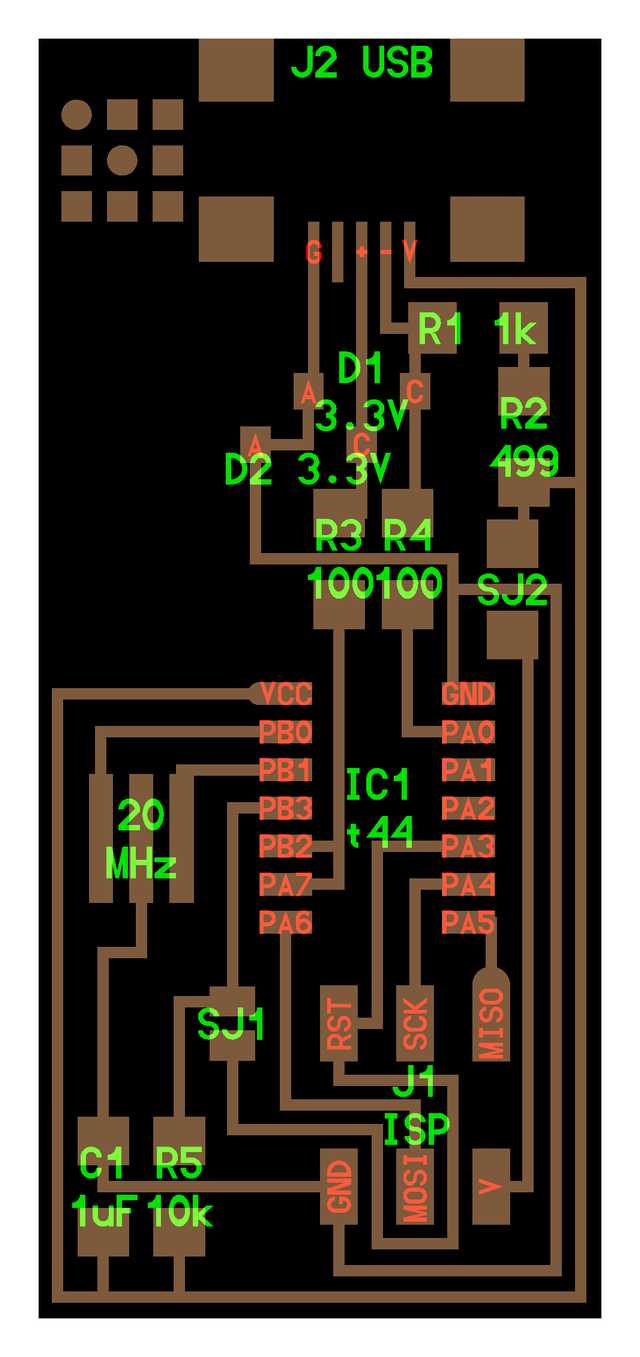
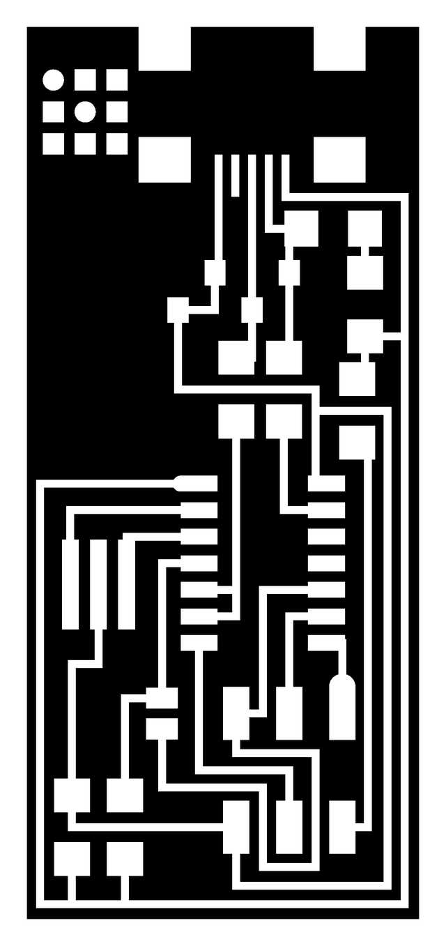
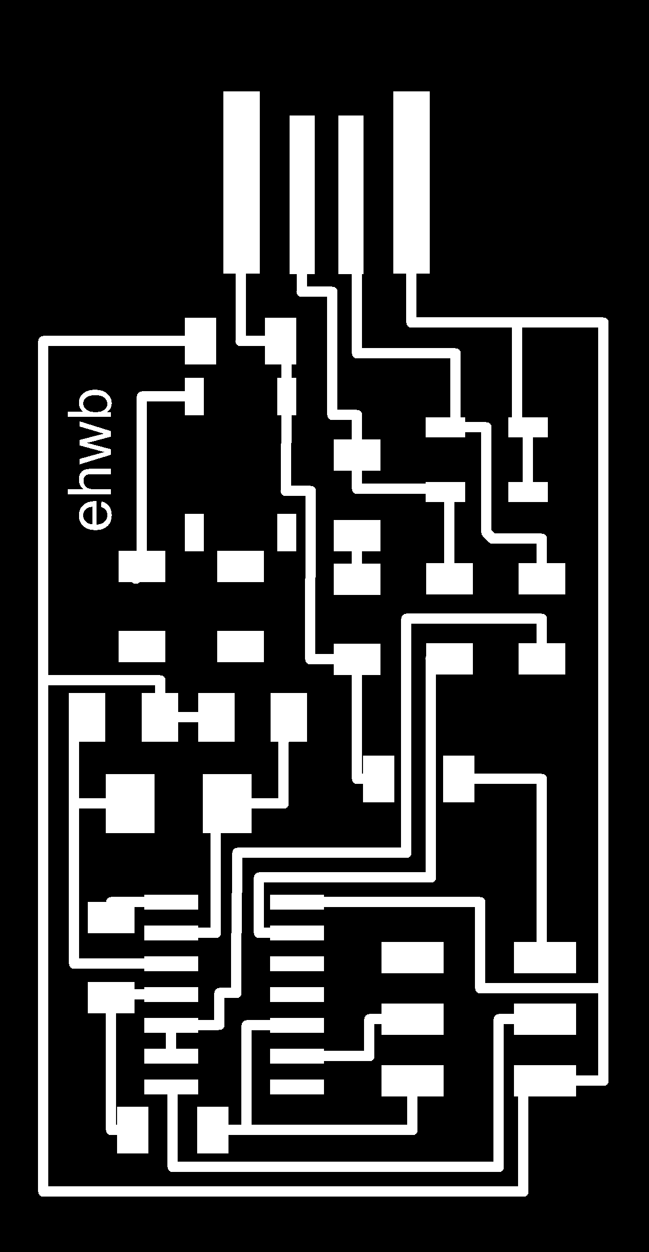
The final board design can be exported as a PNG-image in Eagle (as required from the Milling machine); just be sure to click the Monochrome-box to get Black and Withe and use a high resolution (e.g. 1200dpi). Figure 4 shown the board- and the dimension layer as PNG-input-files for the fab module. Figure 5 shows a path calculation for the 1/64 mill.

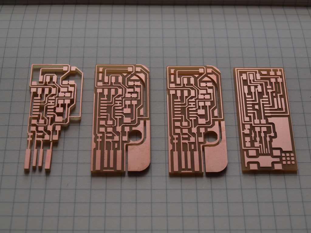
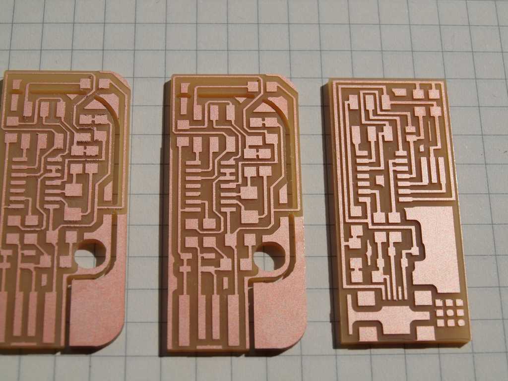
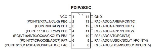
The pictures show the history of my PCB milling success. It started with a misunderstanding: The 1/64 mill is solely used for the traces, the 1/32 for the external; Since I used the trace-png for both mills, I get a nearly free-standing trace structure (left); I then tried Victors design, which was slightly modified and provided by Chikara to avoid shorts (second from left); however, some quality issues regarding the traces lead me to use a new 1/64 mill. The improved results are shown on the right. Standard settings were applied. For more information regarding the microcontroller used please refer to ATtiny44A