the concept
Smart AfricaSmart Africa is a business venture idea I developed within the framework and support from the MIT-class Development Ventures (Fall-2014, instructors: Prof. Joost Bonson and Prof. Sandy Pentland). In short, it aims to produce, distribute, and support an affordable-, reliable-, and sustainable hybrid system providing 1) drinking water, 2) electrical power and 3) light for small communities in rural areas. Off grid and off-infrastructure systems for underdeveloped areas, slums, refugee camps or the like are urgently needed to produce tap water for health, clean and safe light for studying and working, or electric energy for information, communication, and small businesses to enable development and prosperity. SmartAfrica addresses these 3 basic needs in one single system (source: C. Teissl, Business Case, class 15375J Development Ventures 2014).
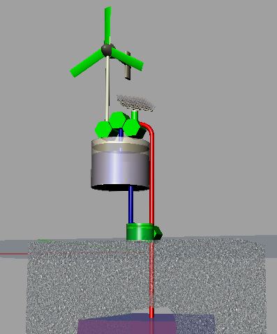
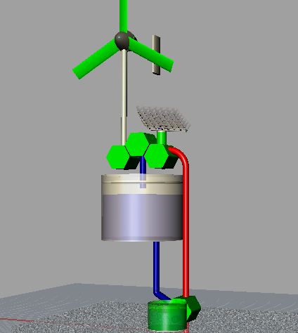
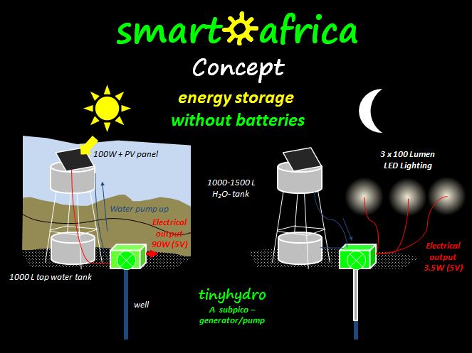
figure 1 and 2 show the concept of the "SmartAfrica" idea; during the day, available contaminated well-or surface water is pumped by a solar-energy driven pump to a storage tank (which can be elevated or on ground level when pre-pressurized), where it gets cleaned. The excess energy can be used for a variety of purposes such as charging mobile devices, driving small equipment, or enabling devices. During the night, the stored potential energy in the water is released and drives a small hydro-generator, which produces enough energy for basic-lighting. This hydro-pump/generator combination, well known from industrial reservoir power stations, is realized with SmartAfrica’s so called tinyhydro. This concept enables doing without batteries, since batteries have often proven to be unreliable under such conditions. In addition we reduce complexity and chemical waste (source: C. Teissl, Business Case, class 15375J Development Ventures 2014).
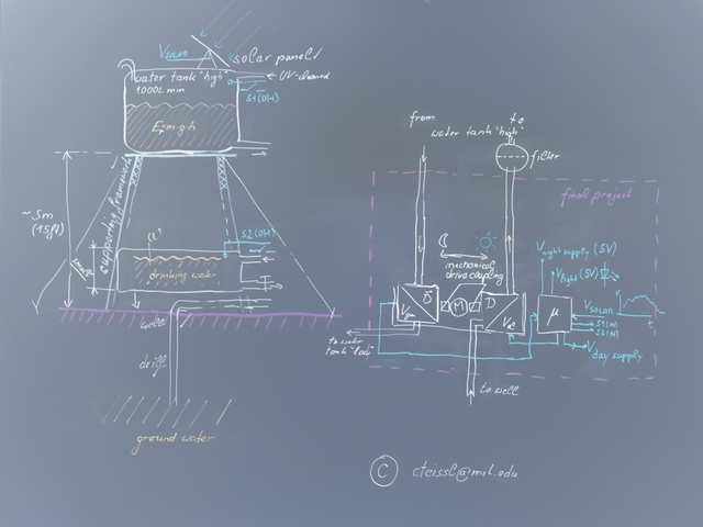
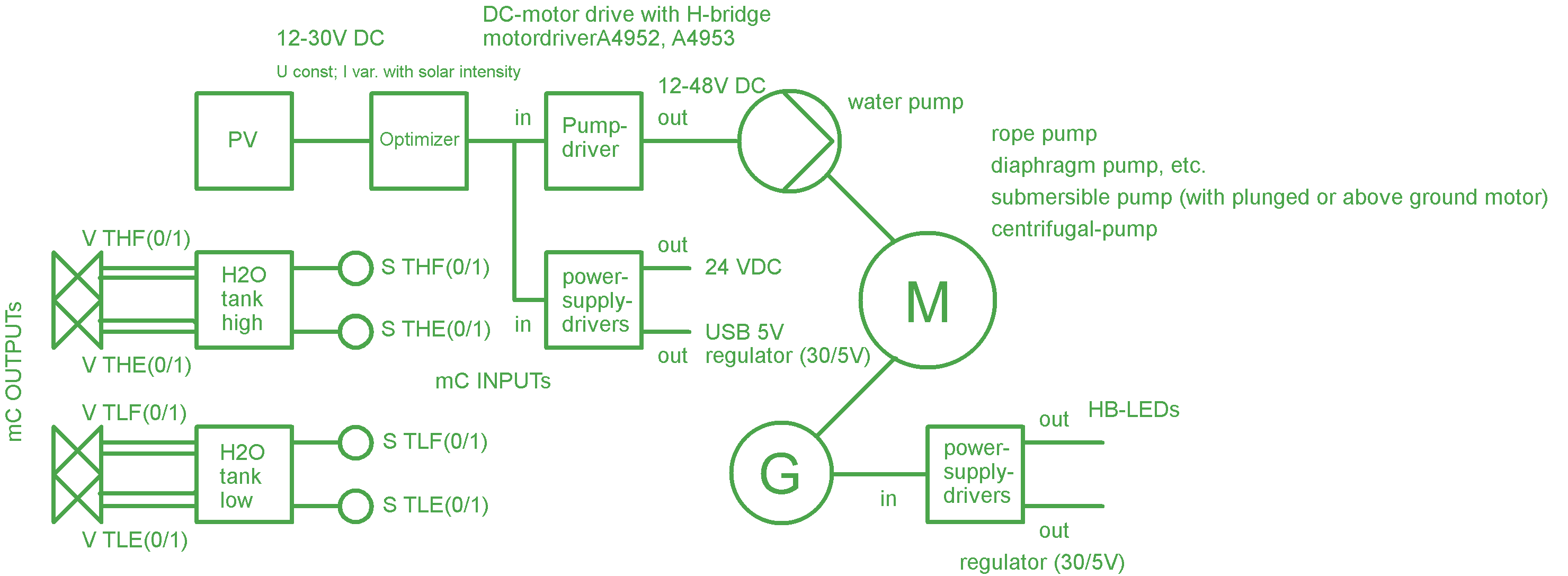
figure 3 shows an electronic block diagram of the SmartAfrica concept: Typically, a 50 to 200 Wpeak Si-Solar Panel will be used generating a voltage between 12 to 36 volts. The generated solar power is used to drive the tiny hydro pump (pump driver) as well as to support electric energy (power supply driver) - the first was realized with a H-bridge in the output-device week. With solar panels, the generated voltage is comparable independent from the varying solar radiation, what varies is the generated photo-current. On the other side, the current needed with a given voltage depend on the load. To optimize the efficiency an optimizer tunes the solar system in the optimum operating point. In the final setup, both, the pump(s) as well as the generator are using the same small dc-motor with permanent magnets. The power (voltage times current) produced by the generator is measured by an ADC-converter, enabling an optimized yield of the produced hydro-energy. Depending on the requirements it can make sense to split the pumping in two steps: elevating the water from deeper wells e.g. by using a motor-driven rope pump, and filling the water tank in a second pumping step).
The main purpose is to drive small LED reading lights. Today, commercial available white LEDs have efficiency between 50 and 150lm/W, if a good color quality (color temperature) is required. This does not include losses; however, when driven by dc directly, as in our case, no losses due to the light engine are present. Therefor it seems reasonable to calculate with 100lm/W. Having e.g. an electrical power of 3.2 Watts over 4 hours at night will result in the capacity of driving 3 white LEDs of 100lm (100lm qualifies as reading light).
Depending on the water tank setup, a possible micro-controller input are the tank-level indicators (full, empty); a possible output is controlling the water valves (e.g. for the pressure tank).
aim of the final project
The final project focuses solely on the tinyhydro, more precisely, on the proof of concept of a small hydro-driven lighting generator/alternator/dynamo, enabling power generation with very low had (and low resulting water pressure) as well as a very low flow rates. The prototype should be cheap but reliable, and set the bases for further optimizing the efficiency. The combination of pumping water during the day and generating power during the night will be realized in a second step, out of focus of the final project adressed here.
small hydro - state of the art
A series of small hydro generators are on the market, primarily from small specialists serving this niche. They are often referred as “pico-hydro”. The main difference to the “tinyhydro” lies in the low flow rate as well as the low penstock-head. In short, the both determine critically the energy output.
E.g., Sam Redfield designed the 5 gallon DIY hydro generator (partly in cooperation with MIT’s D-Lab) for rural areas, using a modified automotive alternator . However, he assumed 30 feet of head and a flow of 26 gallons per minute is required, in order to reach the 13.7 volts needed for 12 volt charging. Though with the tinyhydro the head is e.g. 18 feet, the flow rate is far away from 26 gallons /min; in fact, with a 1000 liter tank you have a flow rate of 4.1 liter/min or 1.1 gallons/min respectively over 4 hours.
In addition, there is a variety of DIY but also commercial small-hydro solutions out there; e.g., Lingenhöle Technologie produces high quality pico-hydro generators using a using a Pelton turbine; the smallest system with 100W was sold in 2013 for 1490 Euro (1860 USD).
the turbine
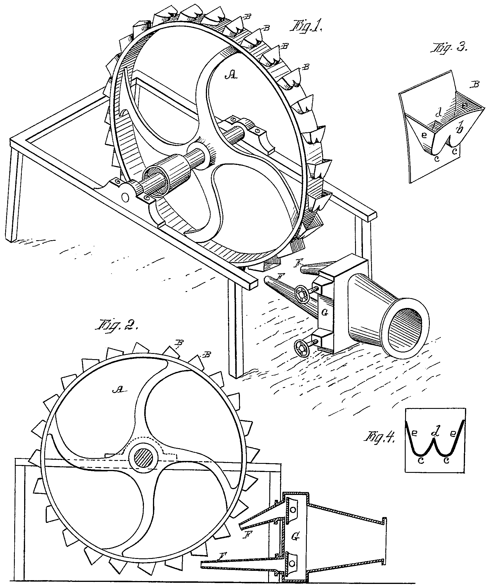
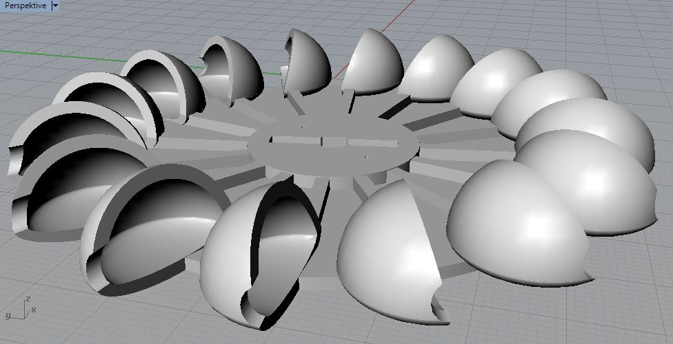
Both, the DIY as well as the commercial variant of a small hydro mentioned above are using a Pelton turbine; the pelton turbine is a impulse type turbine, developed by the US-engineer Lester Pelton – a drawing from the original patent of 1880 can be seen in figure 4.
The water flows in with a high velocity through one or more nozzles and hits the turbine blades tangential to the circumference of the rotor. The blades have a hemispherical shape, and typically are divided by a sharp edge in the center, which separates the water jet in two halves. The hemispherical shapes or cups deflect the water in the reverse direction; therefore, the kinetic energy is transferred to the turbine regarding the “action/reaction” principle.
For an optimal energy-transmission, the rotational speed at the radius where the water-jet hits the blades should be halve of the velocity of the injected water. The diameter of the turbine therefore depends on the alternator RPM and the water-jet velocity.
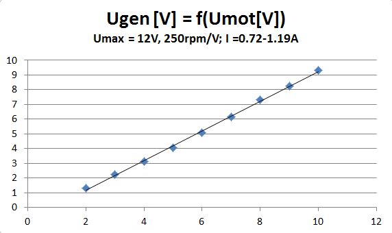
As an alternator, I decided for a “Large DC Motor or Wind or Water Turbine Generator, 12VDC, 1V per 250RPM” (purchased from Amazon for 23.75 USD) – the motor has permanent magnets and 12VDC should result in 2700RPM. To get a feeling for the voltage generated, I used two identical motors and connected the two shafts by a strong adhesive tape. One motor was driven by a power supply, the other motor acts as an alternator whereby the generated dc-voltage was measured by a voltmeter – the ac-parts, measured by an oscilloscope, was about 10%. figure 5 shows that the generated dc-voltage in alternator (=reverse driven dc-motor) is about 1V below the driving voltage; this means that to generate a voltage of about 5V, a speed of about 1200 RPM is required :
- 6Vdc motor input results in 5Vdc alternator output
- 2700RPM (@12V)
- 250RPM/V
- 2700 - (6x250) = 1200RPM
planning the turbine
the dimensions of the turbine were guided by
- the operation window of the 3D printer (which was around 185mm)
- the required rotation speed
- and the alternaor speed.
flow rate
assuming e.g. an elevated water tank of 1000L and 4 hours of reqired electric power during the night, this results in a flow rate of
- 1000L/4h= 250L/h, or
- 4170cmł/min
remember: speed of water jet should be twice of turbine rotation speed, meaning
- 4.170.000mmł/nozzle area = 2 x (rpm x 2rPi)
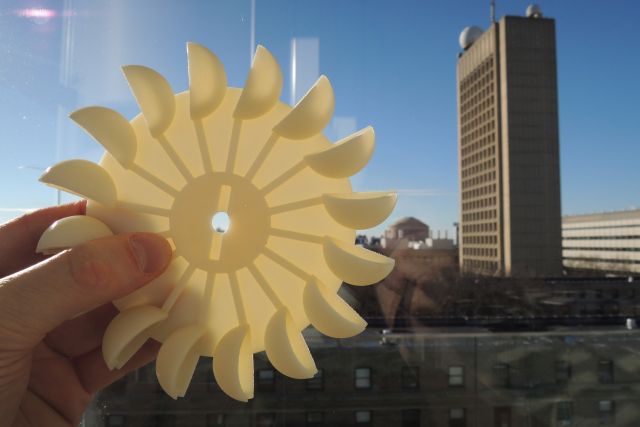
choosing
- turbine diameter:= 140mm
- nozzle diameter:= 3.0mm (A=7.1mm˛)
- idle speed [rpm] = (4.170.000mmł/7.1mm˛)/4x70mmxPi = 668rpm
- 668rpm will result in about (12V - (2700rpm-668rpm)/250rpm) -1V = 3V
increasing e.g. the water pressure will increase the idle speed to 1200rpm, resulting in 5V generated
expected power generated
gross head (maximum available vertical fall): assumed 6m
mechanical power P = g Q p h ef
whereby g = gravity acceleration = 9.81m/s˛, Q = volume flow rate trough turbine (mł/s), p = density of water = 1000kg/mł, h = head (m), ef = hydraulic efficiency of the turbine
- P = 9.81m/s˛ x 0.00007mł/s x 1000kg/m x 6 x 0.5! = 2.1W
According to Lingenhöle Technologie, the maximum total efficiency for micro hydro power plants in the range from 100 to 1000 Watts is about 65 % (taking into consideration the efficiencies of the turbine and the generator). However, the efficiency can fall in case of an unfavorable ratio of water quantity and net head. Therefore I assumed 50% for the calculation above, which can be still to opmimistic.
dimension of penstock
a low flow rate inside the penstock will keep friction losses low!
- e.g. target speed in penstock: 1m/s
- Q = v x A (flow rate of 1000L/4h= 250L/h= 250L/60 = 4.17L/min = 70cmł/sec)
- A = Q/v = 70cmł/s / 100cm/s = 0.7cm˛
- r = 4.7mm (minimum)
- d = 9.4mm (minimum)
- (actual: 16mm)
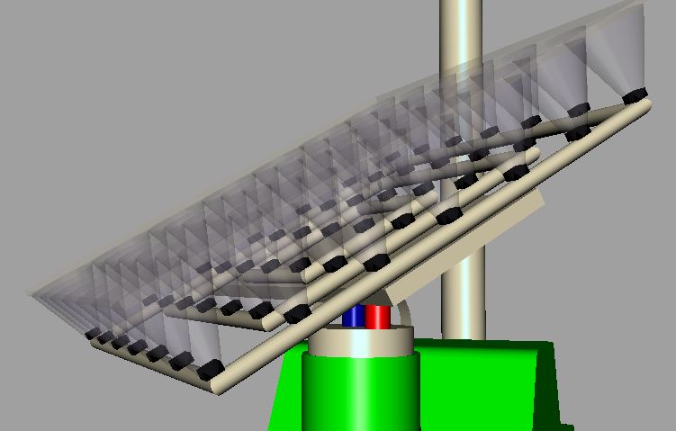
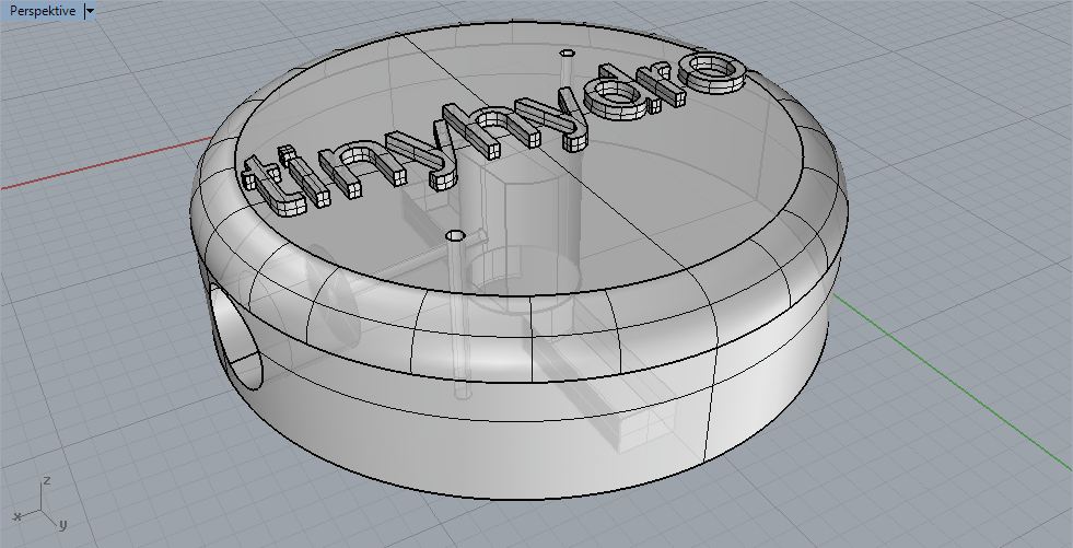
modelling in rhino


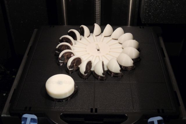
3d printing
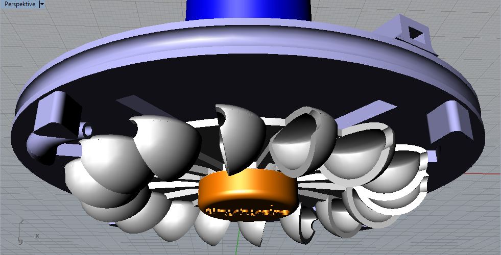
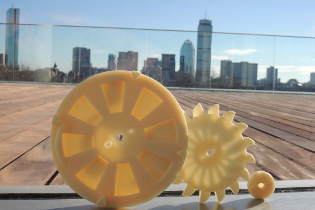
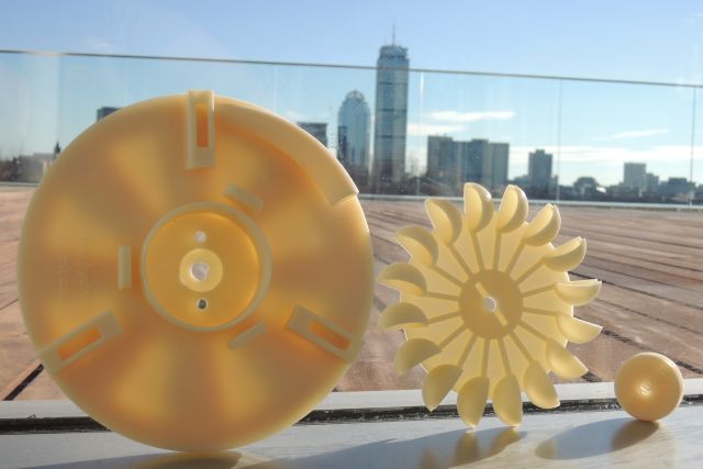
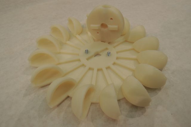
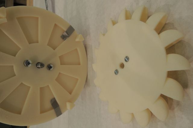
I decided to do the turbine housing as well as the turbine by 3D-printing. A good alternative would have been the shop-bot, however, I wanted to avoid the assembly of too many parts or to have too many finishing steps; the 3D print gave me the possibility to include even the nozzle in just one piece, and the turbine could be made by just one single piece only. It may be added that in principle all parts could be made in one single piece - the rotating parts to get separated easily afterwards.
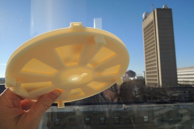
So I designed three parts to be 3d printed, namely the
- generator and turbine mounting
- turbine
- fastening of the turbine to the generator-axis.
ABS-material: For the 3D printer I chose the Dimension Elite which uses an ABS material; this was based on my first small turbine I did in the 3D-printing week using the Invision si2 from 3D Systems (which uses Visijet SR200, an acrylic plastic). Since I wanted to realize a real functioning prototype, where the turbine will get a significant torque and rmp up to 2000rpm, I decided in vavor for the ABS. Also my first experience with the wax as a support material led me to the Elite, which uses a water solvable support material. This promised to be more easily removable, especially in hard accessible locations as the 3mm thin tube to the jet-valve. It turned out that this was helpful.
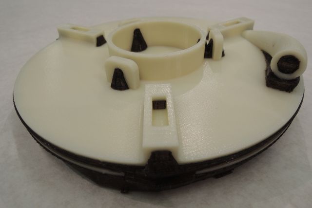
ultrasound-bath: The ABS material proved as a well-fitting material with respect of mechanical properties. Though it takes 12 hours in the ultrasound-bath, finally all supporting material was restless removed (removing residual supporting material after some hours assists to speed up the cleaning process additionally).
For critical dimensions such as the generator fitting I had to do some surface finishing; finally, the generator fit so well that it didn’t need any screws since it was really well hold by the supports alone.
The first model I designed also included the 3 connections to the main-support disc made out of PMMA; however, the calculated print time for the Elite was 90 hours (for the Invision 12 hours); the print-time from the first mainly relies on the print-volume, whereas with the second it relies on the number of slices. Since I wanted to stay with the ABS material I decided to reduce the printing time to at least 30 hours; besides any economic considerations this would enable a 2nd chance for making a modified part if something goes wrong; this was possible by making the three pillars out of laser-cutted PMMA, by reducing the material thicknesses whereever possible and by introducing supportive but thin structures. The resulting printing time came down to 30 hours for the turbine mounting, and to 12 hours for the turbine as well as the fixation (which were printed together).
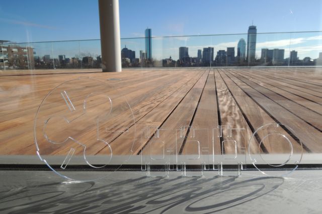
laser cutting
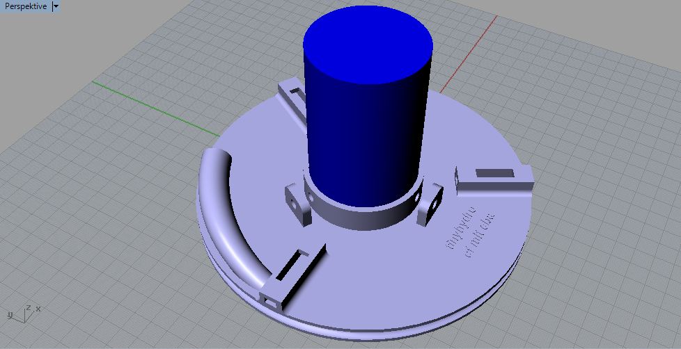
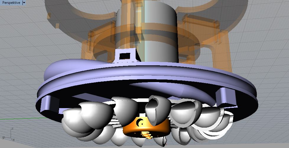
With this tinyhydro prototype, the 3d printed turbine housing is held in place by three connectors, which are mounted to a round plate, inserted into the upper rim of the container (see figure 9, orange parts). Since I wanted to use a variety of different digital tools for the final project, I decided to laser cut this parts.
I selected Ľ inch (6mm) PMMA (clear Acrylic); according to manufacturer manual, Epilog EXT 120W, the power setting for Ľ inch acrylic is 20/70/5000 (speed, power, frequency). Since it didn’t cut through even with 20/80/5000 and 20/100/5000, I simple repeated 20/80/5000 on the same trace with good results.
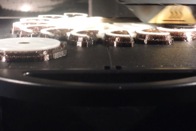
remark: When exporting a Autocad dxf-file from Rhino don’t forget to switch color to black in CorelDraw so that it is recognized as your basic layer; also check if “hairline” is set. The laser cut PMMA parts can be seen in figure 12 and figure 13.
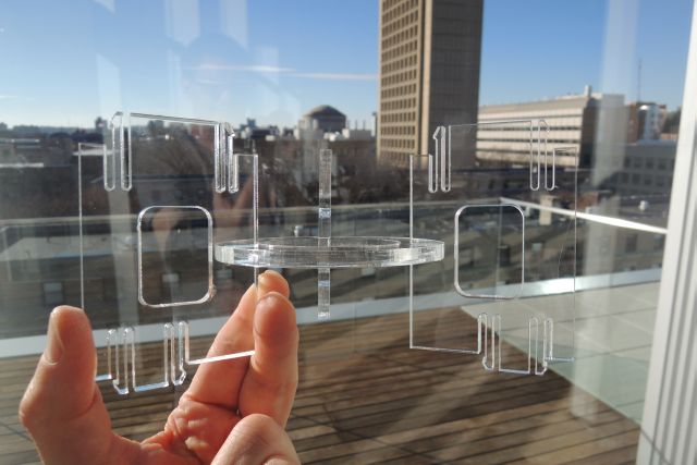
the following learnings from the first run of acrylic press-fit test can be drawn:
- laser track width is 1mm centered in given trace
- for for flexible parts, 2mm displacement is too large at least for short radii such as 15mm – make 1mm only
- 2mm thick, 18mm long flexible structures break easily - 1.5mm seems to work
- for flexible structures at 6mm PMMA and 1mm flexibility: 1.5-2,0 mm thickness and at least 18mm long
- add at least rounding’s (instead of biomimetic tree-like structures) to reduce stress, and make thicker part as short as possible
- Make more parts to have back up!
In conclusion it should be noted that PMMA was probably not the right material for this press fit structure; though it looks great, is very stable and the fittings where so exact that no other mounting such as screws where needed, the material is just too brittle and cracks very easily without indicating if stressed too much. It would have been interesting to have a look at the stress-behavior under crossed polarizers, which I didn’t do this time because of time pressure. However, for a second prototype I would recommend to use an alternative, more flexible material.
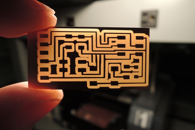
electronics
hardwareSince one option for the input- and output device assignment was to use one required for the final project, I planned sone time ahead and selected and ADC-converter for the input- and a PWM-motor drive for the output week (the later for the pump-option of a tinyhydro version to follow which can work in both directions).
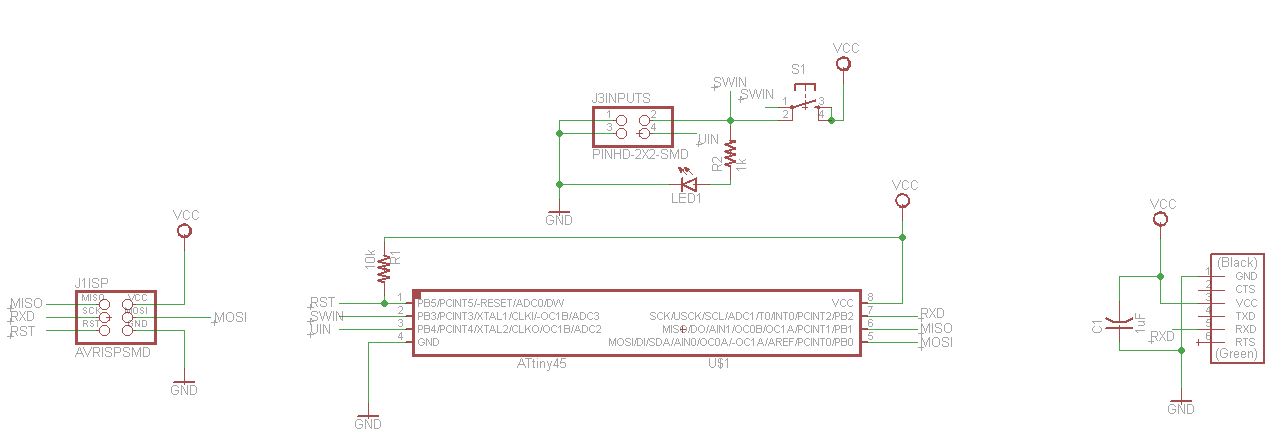
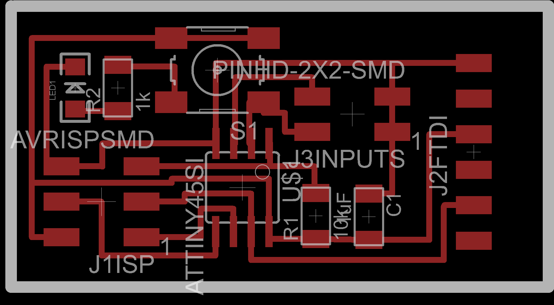
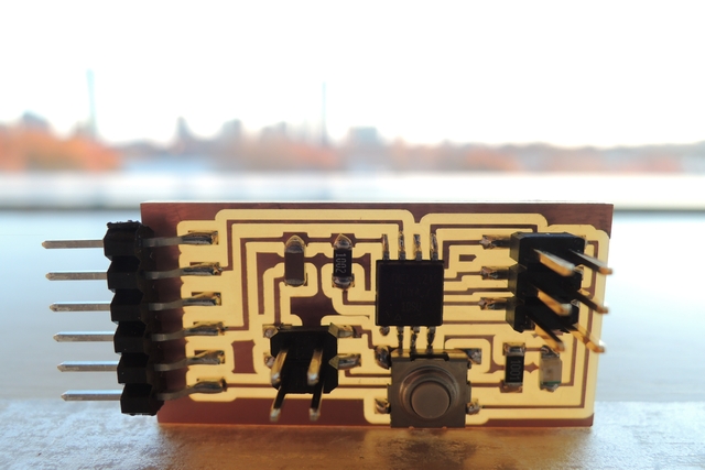
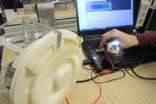
the same is true for the interface software; The main output of my small machine, the tinyhydro is power; However, here I reduced the application to indicating the voltage of the generator; in this application only to the reference voltage of 5V, however, this could be extended easily. Together with a super-cheap LED camping light, this are my actual indicators of genereded voltage and power respecivele. Please find the source code of the small python prgram here.
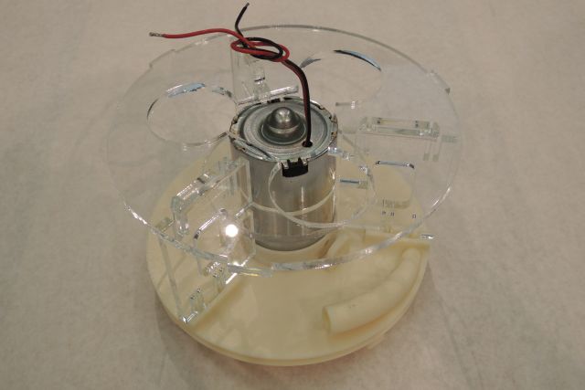
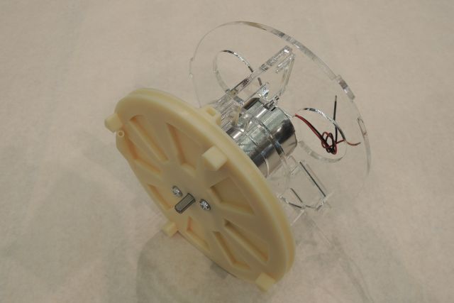
the tinyhydro assembly
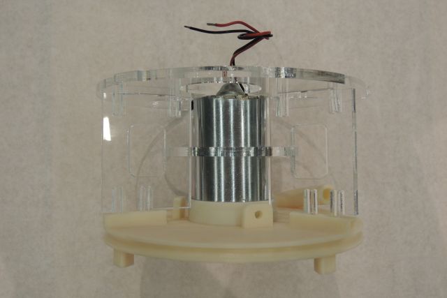
proof of concept
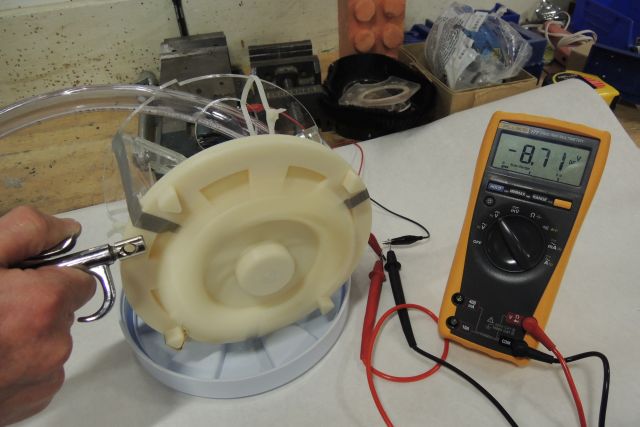
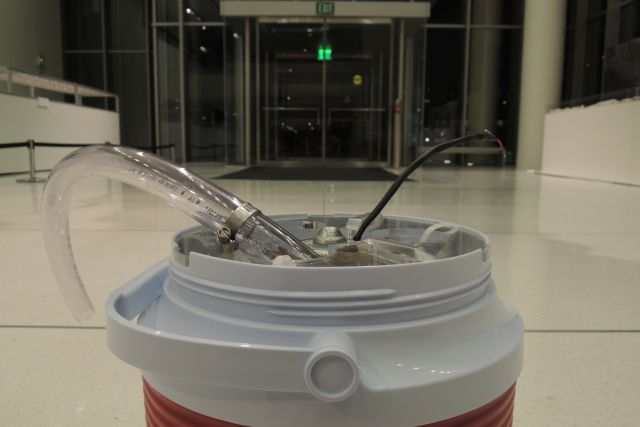
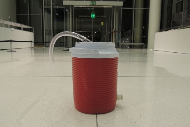
the first proof of concept PoC step was done under real wet conditions; I used the water connection from the water-jet - though I had no proper connection part at this time I had to improvise; using magic-tape results in a quick and dirty connection, which was pretty tight in the lower pressure range; so the water flows from the water-jet connection in the tinyhydro, and then back to the water jet basin. Sitll, also With only comparable low pressure we (Jonathan B and Palash N. were so kind to assist me) reached 3V in the first run; since we used only medium water pressure under not jet optimum conditions, this result makes us curios what we could archive - and so we tried it out with the air-jet where we could reach 9V (see below). 9V equals to about 2250-2500 rpm, since the DC motor I use has 250rpm/V, and the generated voltage always was about 1V lower than the voltage of the motor I coppled in a first try-test to the second motor used as a generator (of identical type).
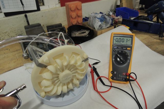
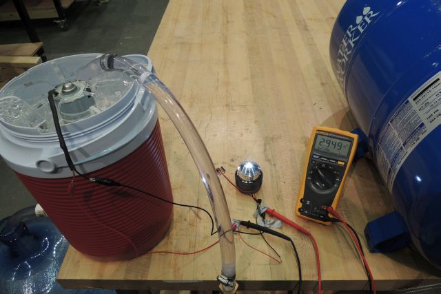
the 4th PoC was the demonstration of our final projects in the 6th floor of the Media Lab (Dec. 16) - this was very exciting since I had not the chance before to test the tinyhydro together with the just delivered pre-pressurized water tank. Since there were only one hour left to fill the water tank and there was no water pump around, I used again the host from the water jet; however, this only works until pressure equilibrium is achieved and this was around 40psi (the water tank used is built for loads up to 120psi); so we had only about 4 gallons of water with a pressure of 40psi (2.76 bar), with that I went to the final presentation; I'm happy to say that everything went well - opened the valve of the water tank, the turbine stated to torn the generator, the LED lighted up, the voltage could be rad on the PC.
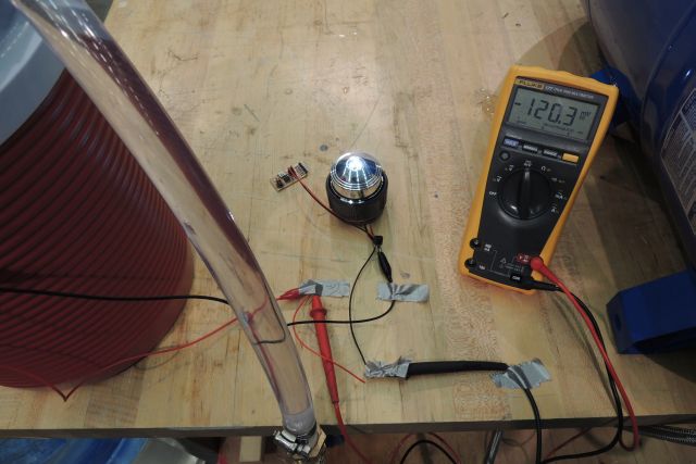
On the next day I repeated this experiment to measure the power produced as well as the water flow needed; it was the same setup as the day before, this time I measured the produced generated voltage with a voltmeter (since my laptop didn’t work), and the current I measured via the voltage trop of a 10 Ohm resistor. The voltage generated was nearly 3V, the current about 12mA (120mV/10Ohm) - resulting in 36mW. The water flow was 1 gallon per minute (3.8 liter/min), which equals the target value of producing power with a 1000 liter water tank over 4 hours (1000l/240min).
Though the reached power in these first and quick PoC tests is far away from the some watts possible, now, in having done the design and rapid prototyping, I know the larger and smaller screws to be turned to increase the efficiency- and this will be a task for future work.
the original concept