input devices
some thoughts on the general input- and output requirements for the final project
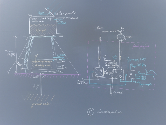
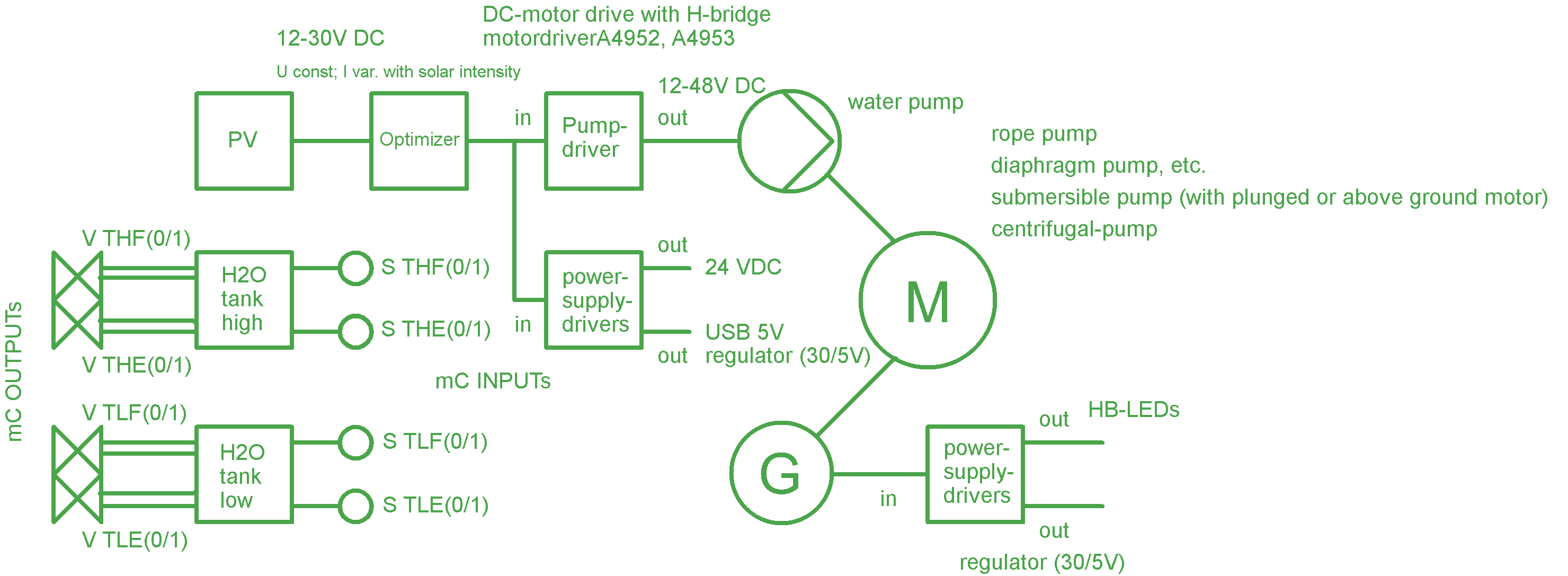
This week I had to decide which part of my "solar driven water- and energy supply system for rural areas-project (for further information please refer to my final project page) I would like to focus for my final poject. This week's (input devices) as well as next week’s project (output devices) - which can be combined and used or the final project - gave a good opportunity to think about the function of the final device - and here especially regarding its requirements from the electronic side. So I had to choose between realizing the PV-system or the hydro-generator/storage-system system; for some reasons (mainly relevance and USB for a further implementation) I decided for the later one. Figure 1 shows a first sketch I did on the electronic inputs and outputs, figure 2 shows a referring block diagram.
input-requirements
As obvious from figure 2, the inputs from the hydro-generator/storage system are from two sorts:
- sensor inputs from the water tanks, indicating the respective level of the tank (e.g. 10%, 90% capacity) - this can e.g. be switches or 0/1 input signals
- voltages, such as the voltage from the the PV-cell or the hydro generator.
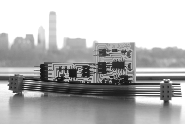
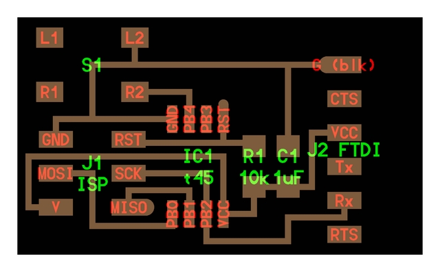
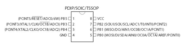
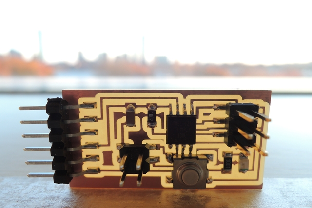
From that it seems helpful to have a closer look at Neils hello-button.tiny45-board (see figure 3); the pin-configuration from the tiny45 can bee seen in figure 4.
designing with eagle
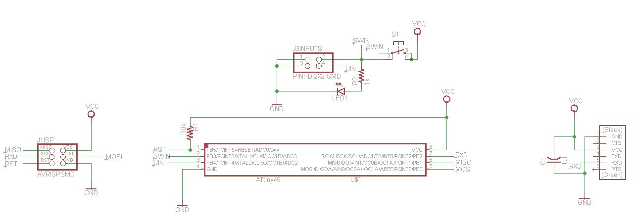
figure 5 shows my schematic design in eagle; please note that the original hello-button design links the button to the PB4-pin (to ground), whereas in this design the button is connected to pin PB3 and to VCC - which hast to be considered in the test program. It also can be simulated by just pulling pin PB4 pin to ground (PB4 is lead trough to J3/PIN4). I used pin PB4 as an additional input/output-pin to communicate with my output-board.
Regarding eagle I learned two new things worth noting:
- first, define the grid before starting to work on the schematic - if you change it during the process, you will have to move the parts so that they can link to the new grid, otherwise linking the parts can be difficult or not possible
- when being ready with the schematic to generate the board, make sure that you did the "show test" carefully; you will probably do it with VCC and GND, however, it happens easily not to check all labels for instance; if this happens, it could be easily overseen because the "not connected" (and therefore the ratsnest-test) is not aware about this required connection.
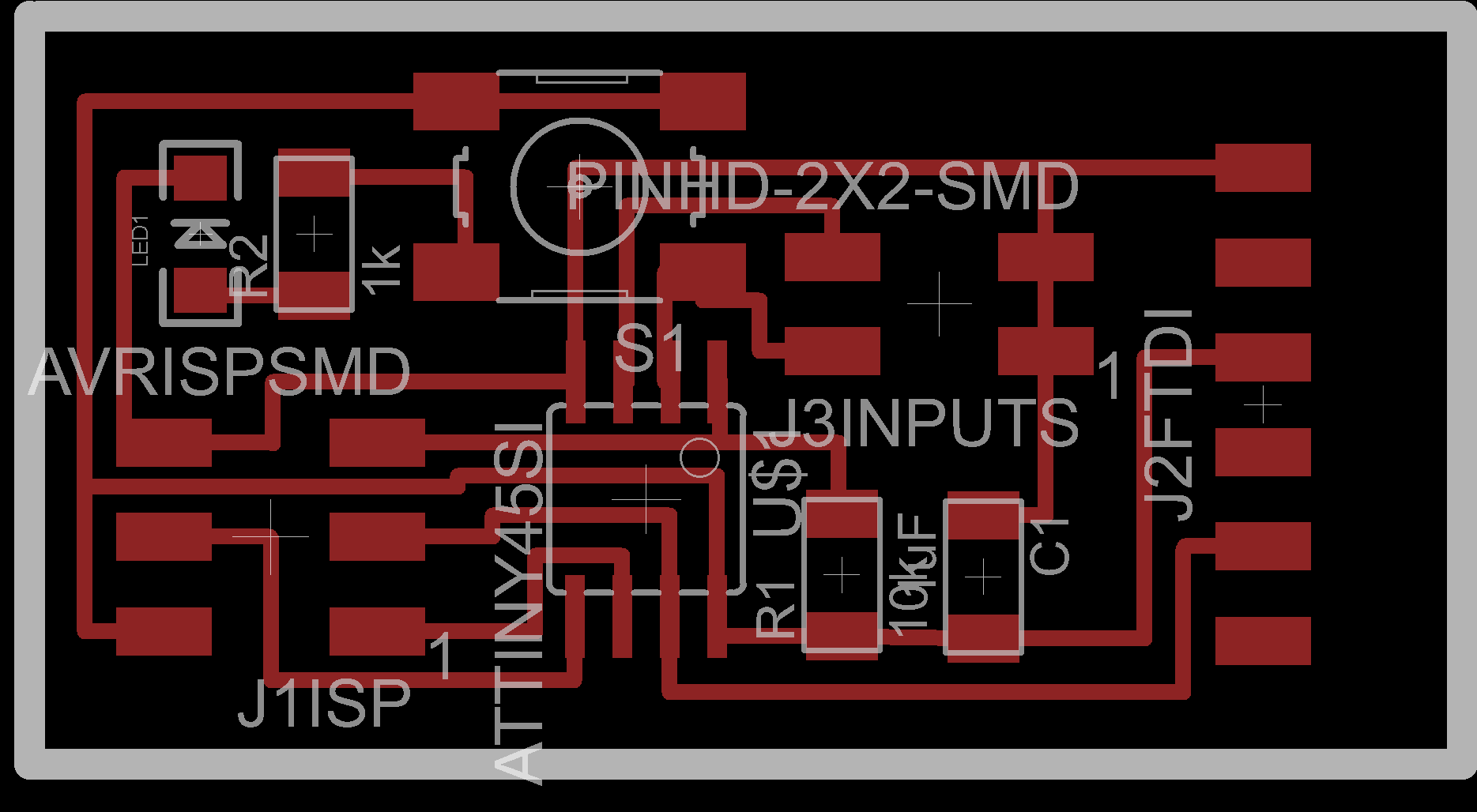
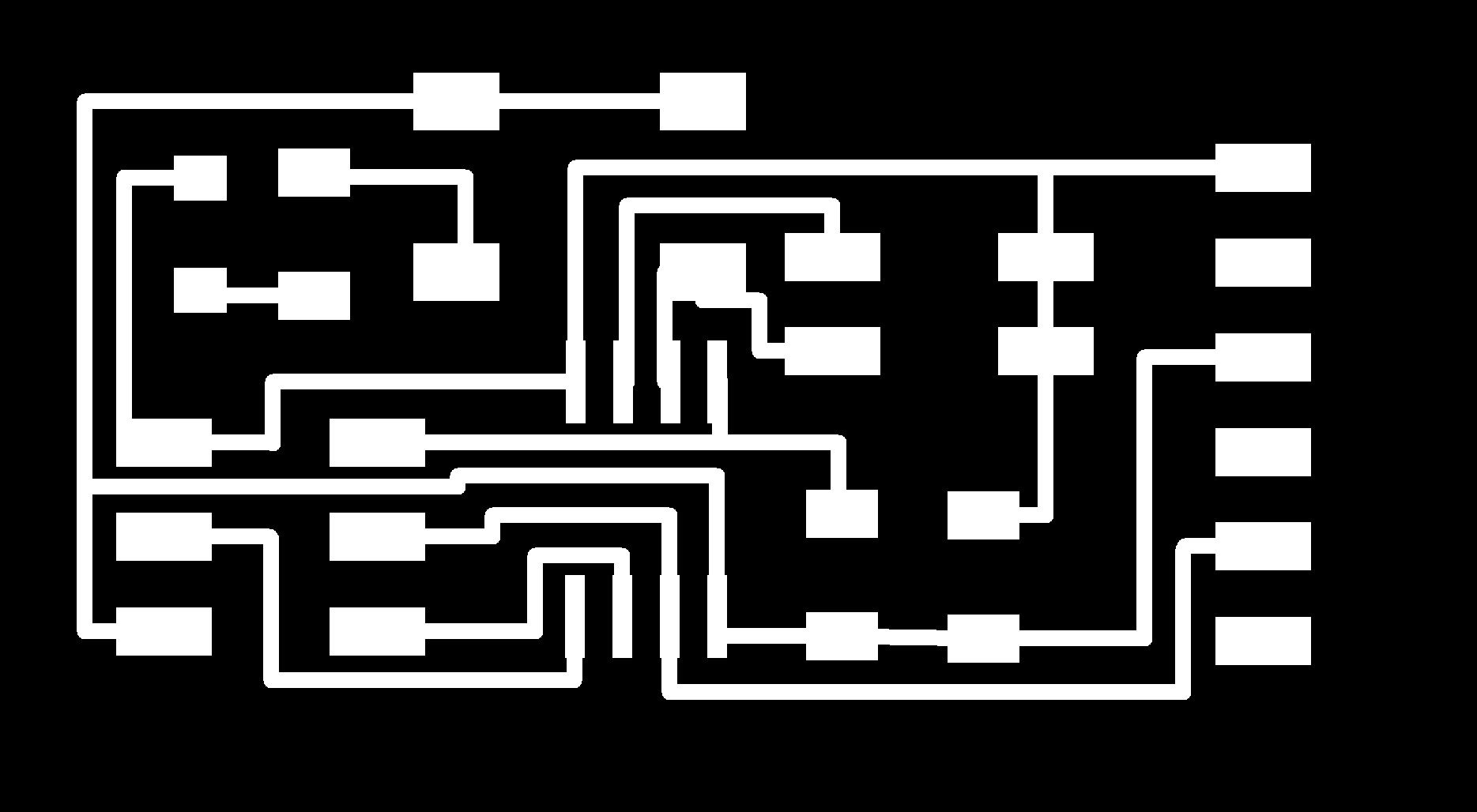
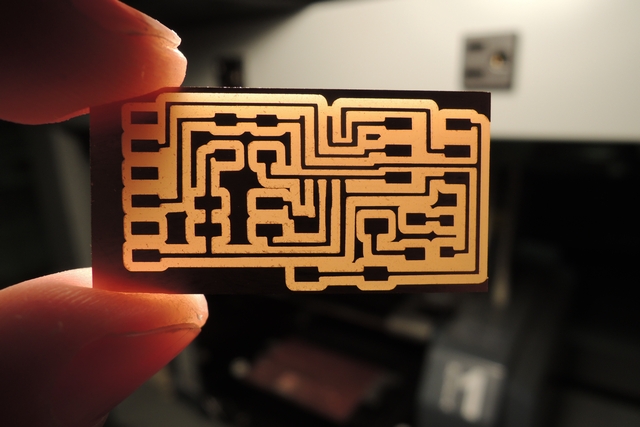
pcb - ready for milling

testing the board
pre-programming
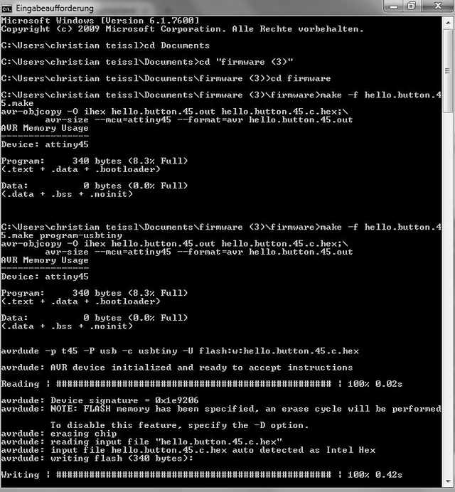
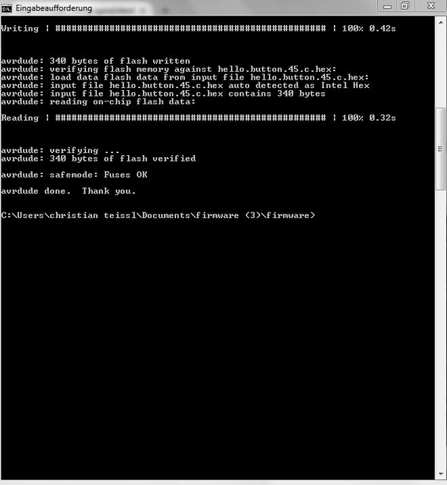
to test the hello-button board I downloaded the two respective .c-file (hello.button.45.c) and .make (compiler) files (hello.button.45.make) from the class-page and connected the new board with my fab-isp. Then pointing in the terminal to the directory containing the files mentioned above, I run the following programs:
1: make -f hello.button.45.make //does the compiling - watch for error messages
2: make -f hello.button.45.make program-usbtiny
successfuly pre-programmed!! - as can bee seen in the prompt-message below (figure 9).
testing
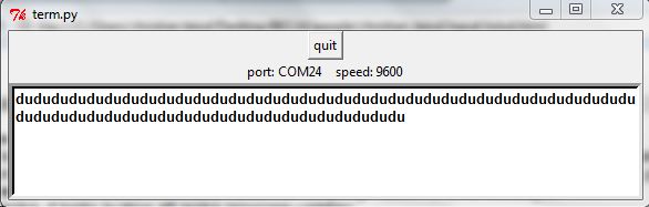
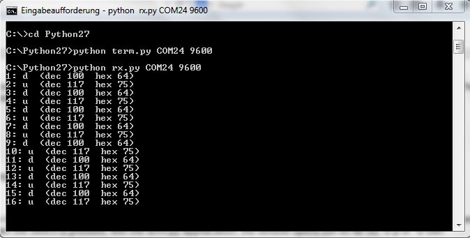
- step 1: install pyserial-2.7.win32.exe (already done for the hello.echo program in the embedded programmin week) - otherwise go to pySerial 2.7 documentation page
- step 2: download python files rx.py and term.py from the class page
- step 3: from the prompt run: C:\Python27> python term.py COM24 9600
- step 4: from the prompt run: C:\Python27> python ry.py COM24 9600
remark: the baud-rate can be seen in the hello.button.45.c-file (9600 baud FTDI interface)
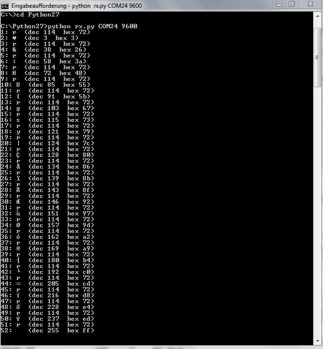
result: Since in my application PB4 was connected to the button and not PB3, I just pulled PB3 down to ground using a cable which I connected to ground and then hit the pin at J2 representing PB3 - this seemed to work out fine for a quick and dirty test; both applications run - button down and up are recognized and the characters are sended back to the computer; please see images below. I a next step I modified the program slightly to it works with my outline
programming inputs
Function of the program: There are two inputs, a switch and an analog signal; I wanted to experiment with the build in ADC from the ATtiny45. Pressing the button leads to a sample-and hold event, releasing the button sends the register-values via the serial interface to the computer (Neil’s python program rx.py), where the received ASCII or HEX data can then be recalculated to voltage levels. Going through the ATtiny manual gives you a clear picture how the ADC-process works and registers have to be addressed:
initializing the ADC
ADMUX Register
- If not all 10 bits are required, set 8 bits only, so you just have to read out the ADCH-register (ADLAR = 1)
- set the reference voltage by REFS[2:0]; for REFS1=0, REFS2=0 VCC is the voltage reference
- set the analog input channel; for my case its PB4 as single analog input: MUX[3:0] = 0010
ADCSRA – Register
- set the ADC enabled via ADEN
- set prescaler 8000kHz/64=125kHz via ADP[2:0}]=(110)
this took me a while to find out since it didn't really attrac my attention in the manual; though it seems logical that an ADC needs some cycles to convert the signal, the clock for the ADC should be below 200kHz; Since by default the internal RC oscillator provides an approximate 8.0 MHz clock, a good value for the prescaler is 64
- start measurement by setting the ADC Start Conversion bit (ADSC)
- When conversion is complete, the result is written to the ADC Data Registers, and ADIF is set. In single Conversion mode, ADSC is cleared simultaneously - so wait until ADSC is cleared
you can find the c-source code of my program here: c-file
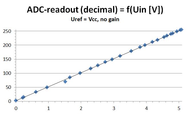
figure 10 shows my brief ADC-program; when a button is pressed, a single ADC-communication is triggered – in proof of concept condition; the voltage on a manual potentiometer is measured at the PB4 from the ATtiny45. Then, when the button is released, the ADC-result is read out and sent to the computer via serial communication. Here I relied on the python file (rx.py) from Neil. I used VCC as reference, the potentiometer was also fixed on VCC, so the sliding contact can be tuned from 0 and 5 Volts. The read out correlates nicely with the angle of the potentiometer, starting from 0 and ending at 255, which correspond to Voltage (in mV) = x times 5/1024 times 4.
To verify that I then measured the input voltage to the adc; figure 11 shows the measured calibration curve - the dependency of the adc decimal readout as a function of the input voltage.
From here the program can now be easily expanded to read in a variety of measurement signals on the input side for different applications. In my case I'm interested in the actual power of a solar cell driving my solar pump and micro-power station, and especially knowing the actual power of my hydro driven micro-generator (please refer to final project).