networks and communication
serial asynchronous hello bus 45
Since I am a novice in micro-controller networks, I decided to focus on Neil’s hello.bus concept and use it as a good learning environment. In addition I appreciate the modular concept of having individual, distributed microcontrollers, since it seems help reducing risk in prototyping. So I wanted to understand the basic concept behind and its working principle. So I started with some reading on a variety of micro-controller tutorials and platforms. Please find a brief summary in the following which might be useful for beginners.
RS-232: Of course we all know the serial RS-232-connection - but also the protocol and the basic function? The bit-serial information flow uses two data line, one for each data transfer direction (RxD, TXD). Since the microcontroller works parallel, the serial-parallel transformation is performed by an UARTs (Universal Asynchronous Receiver Transmitter).
Asynchronous means that there is no shared clock - instead, each node can send its full-dataset if the line is free. The synchronization starts then by receiving the first start-bit (triggered by the slope); the stop-bit has the inverse level of the starting bit. Therefore the receiver synchronizes itself withon the mean of each data-bit (this requires that the bitrates from transmitter are and receiver do not differentiate from each other too much)
Each transmitted word starts with a start-bit (equals to logic 0), and end with a least one stop-bit (logic 1) – for at least 1.5 bit-lengths. The information in is transmitted between the start and the stop-bit.
In the following I will go trough the designing and production of the hello.bus - network. At the end you will find my small c-file modification, which enabled me to address the three nodes individually. From there it seems feasible to explore the wide potential lying in this technique.
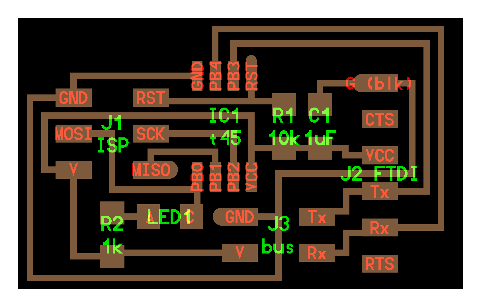

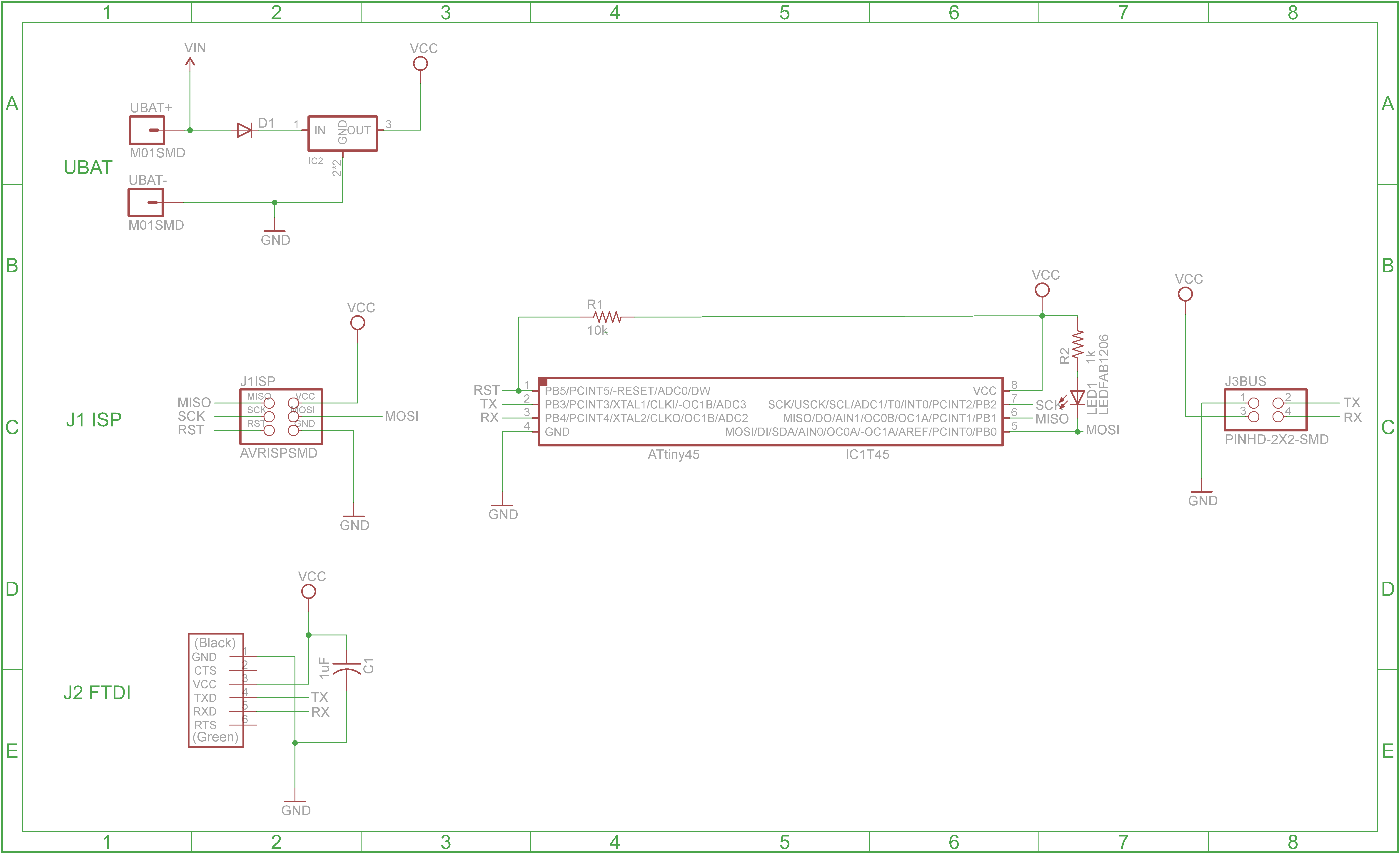
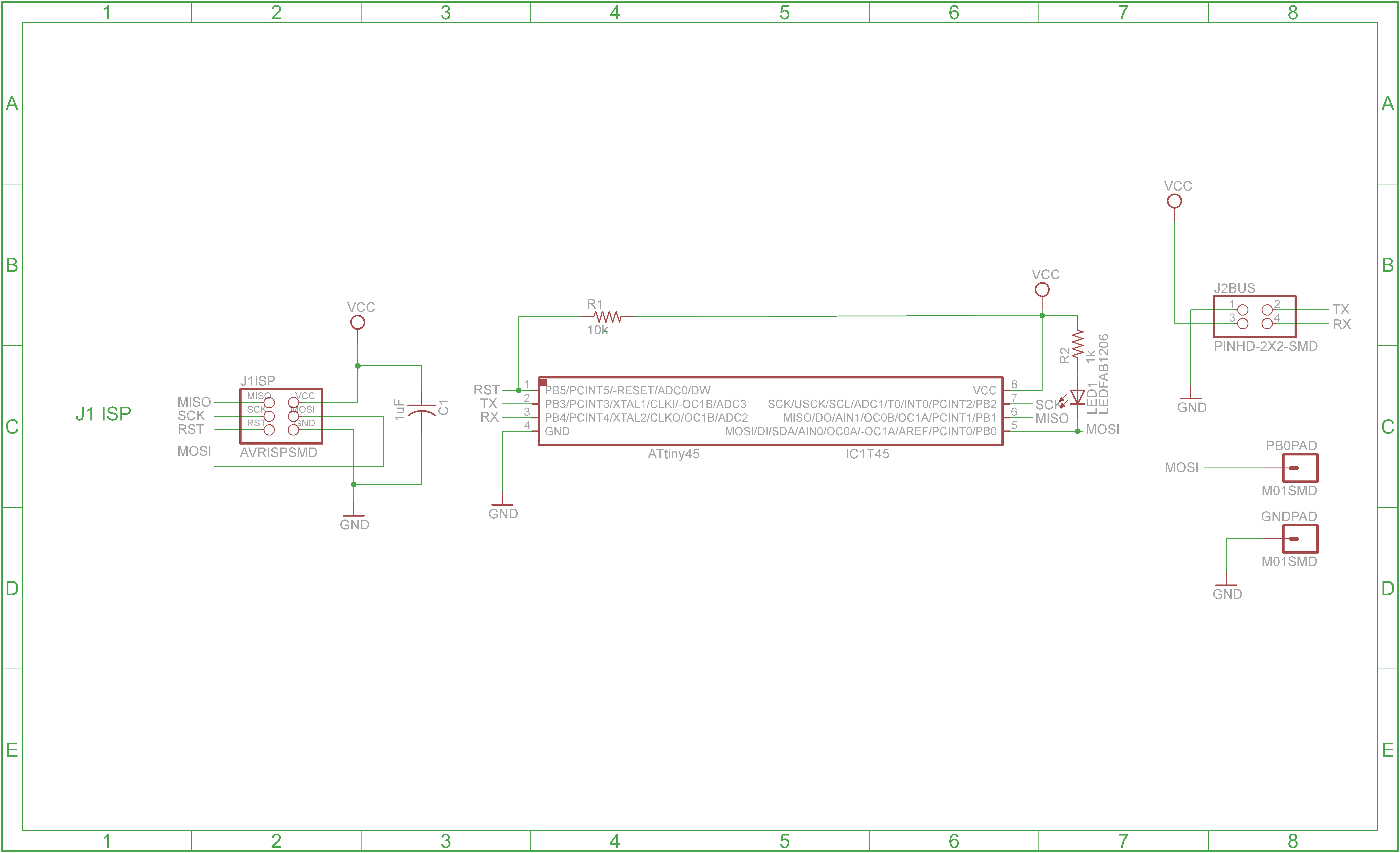
bus bridge 45 schematic
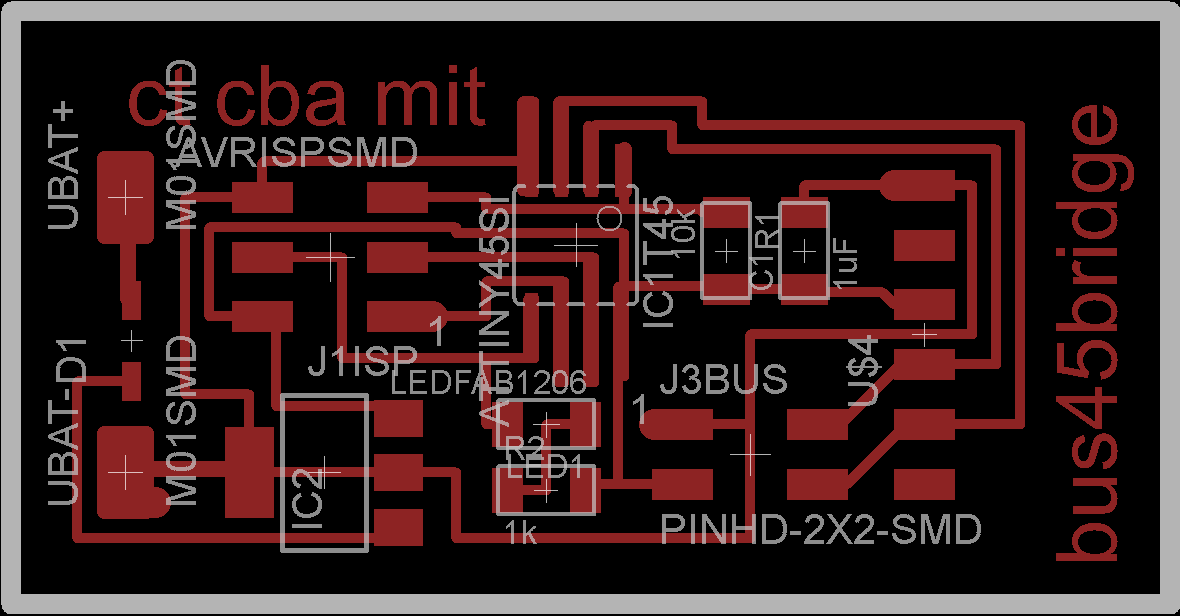
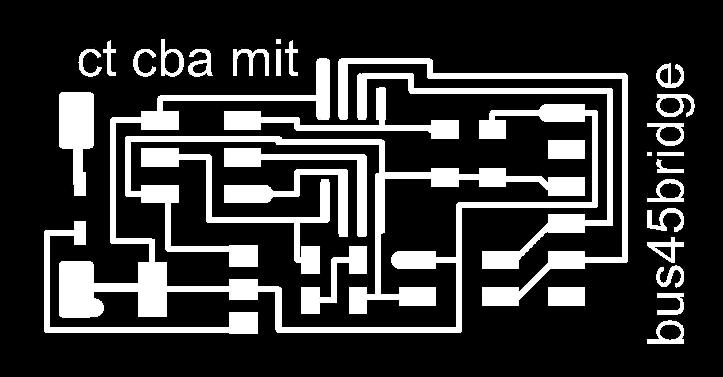
bus bridge 45 board
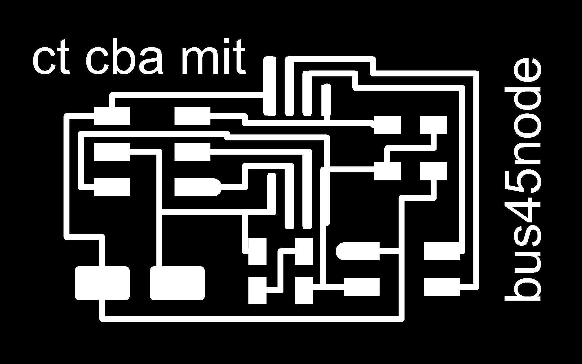
bus node 45 schematic
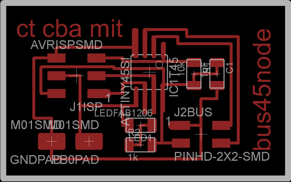
bus node 45 board
milling the boards
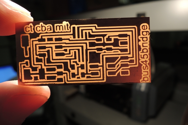

From the basic layout it is obvious that the three boards are identical from their electronic function. I did some minor changes, such as adding battery or power supply contacts, a voltage regulator as well as a protection diode to the bridge board. With the two nodes I added to pads to GND and PB0 so to be able to add additional input or output devices for later modifications. The milling was straight forward, however since the 4 traces under the ATtiny45 make spacing already comparable challenging. It pays to have a careful look on the trace calculation from the fab-modules to spot possible shorts. With the 1/64 inch mill you will possible have a few, so I often reduce the spacing from 0.4mm (corresponding to 1/64") to the maximum still possible - which is typically around 0.3mm; this might result in thinner traces but worked out fine the last times. I also make the check with a lamp afterwards, where short can be easily spotted. In addition I always check the board under the microscope, because often there are some very small milling rests or fine copper rests easily leading to shorts or having not a good connection to the board. With the two node-boards you can also see the quality difference using an old (left) and a new (right) 64"mill.
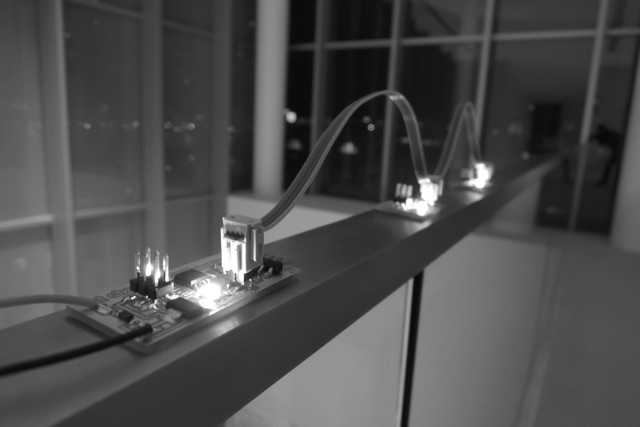
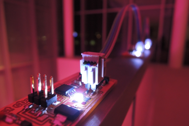
stuffing and testing
After stuffing I tested the hello-bus network. You can see the linked network in figure 9 and 10.
programming the boards as mentioned the 3 boards are electronically identical, whereby the bridge board allows a serial connection to the computer. The following steps are required
- connect the first board (e.g. the bridge) to the Fab-ISP
- run: make –f hello.bus.45.make followed by: make –f hello.bus.45.make program-usbtiny
- connect the first node board to the Fab-ISP
- connect the next board (e.g. node) to the Fab-ISP
- connect the first and the second board via the 4-pin header
- run: make –f hello.bus.45.make program-usbtiny
- connect the next (final) board with the Fab-ISP
- connect now all boards with the 4-pin header (they can also be connected at the beginning)
- run: make –f hello.bus.45.make program-usbtiny
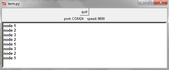
Finally run the python applicationa: python term.py COM24 9600
result:
- pressing “0” results in 2 short “simultaneous” flashes at all 3 LEDs
- pressing any other character results in one short “simultaneous” flash at all three boards
it works!

programming
With Neils hello.bus program the parallel to serial transmit/receive is performed by the two functions put_char and get_char respectively. As we just learned above, we need a start bit (put_char) or have to wait for it (get_char). We also send a stop bit after the char is transmitted (in our case we don’t wait for the stop bit since the message is always only a byte long), and a brake of at least 1.5 bit length is guaranteed. The bit length is generated by bit_delay().
The main loop
Since we are also connected to the computer, we have actually 3+1 nodes; after the initialization is once done, we are captured in the main loop. The three microcontrollers listen on their PB3 pin which is set as an input and connected to TX (in the perspective on the computer) until a character arrives (is typed in); this triggers the first flash. Node ID is defined here as character '0'; so if '0'gets typed in, a second flash happens.
Though I have worked with pointers decades ago, I had to refresh my memory a little bit – to understand Neil’s program I found the following helpful:
- a pointer is a variables whose value is the address of another variable, i.e., direct address of the memory location
- they allow a dynamic memory allocation, which cannot be performed without
- an address is accessed using ampersand operator
- to declare a pointer variable you use the asterisk *character
- since the pointer is an address an therefore an numeric value you can perform arithmetic operations on it
- the attribute progmem tells the compiler to place the data in the program memory (flash)
- static const char message[] PROGMEM = "node "; // explicit declarations for char to put it in Program Space
- put_string //PGM_P is a macro defined as a pointer to a character in program space
- pgm_read_byte in “put_string” read a byte from the program space with a 16-bit (near) address (address is a byte address and in the program space)
in the following I modified Neil's hello.bus program slightly to receive the following function:
- pressing '1': the respective node #1 responds by flashing one time only - the two other nodes stay silent
- pressing '2': the respective node #2 responds by flashing two times, the two other nodes stay silent
- pressing '3': the respective node #3 responds by flashing three times, the two other nodes stay silent
- pressing any other character gets ignored
From here it seems feasible to experiment with a series of communication variants from node to node as well as addressing different tasks to the nodes and collecting results..
The c-program can be found here.
Here the motivation was to have a comparable simple possibility to assign a task such as being a step for a stepper motor to 3 different nodes representing the coordinates X, Y, and Z. An application could be a simple 3-axis gantry system. Again, each node gets an ID, however, first the user (or a program) has to type (or send) any number from 0 to 9 (could be steps etc.) – to program waits until the send character equal’s an number; Then, the program expects the axis: a character x, y, or z must follow - all other characters get ignored and the program will wait until the information required is typed or sent; To check if the program works correctly I used the LEDs of the nodes; number of blinking = 0 to 9; node = x, y, or z; The c-program can be found here.