embedded programming
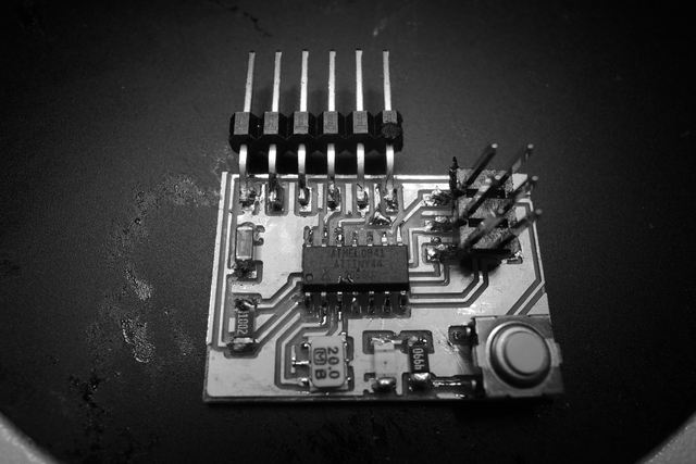
fab-isp
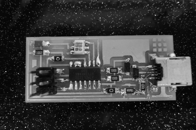
The fabisp is an in-system programmer for AVR microcontrollers. It's based on the firmwares USBtiny and the V(virtual)-USB . They allow the ATtiny44 to perform USB communication. Programming can be done through avrdude (which is included in the WinAVR)
extended smoke test
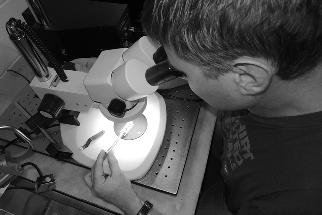
Before I connected my ISP the first time to my computer, I inspected carefully for shortcuts using the microscope. Then I used a USP-power supply with an automated current limitation – since it gets activated, I checked the input resistance of the circuit; it was about 300kOhm, which corresponded to the working ISP module from Dan. I checked the diodes (2 Zener, 1 LED) with the Voltmeter in the “diode-testing mode” – also negative. So I switched the USP-cable – positive; using a different USP cable supplied the ISP board.
In addition I also checked the supply voltages on the hardware interface and the microcontroller, as well as the 3.3V at the two Zener-diodes (USB-data-lines). Since I couldn’t detect any 20MHz-timer frequency with the oscilloscope, I assumed that this is because the microcontroller is not programmed yet and the pins provide to signal.
programming the fab-isp
For programming the FabISP I may point to two tutorials:
fabisp, a fab-able in-system programmer and
how to assemble and program the fabisp.
Installing firmware: firmware.zip.
Installing WinAVR: WinAVR is used as development tools for AVR microcontrollers – this can be downloaded from AVR Setup, avrdude is included (just test it by typing avrdude in the command line).
Connecting the ISP (not programmed yet) to my Laptop - a new however unidentified hardware is detected - OK
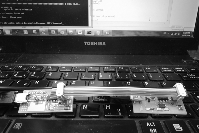
Try 1: To power the board I pugged the mini USB connector for my not yet programmed FabISP into my computer. The separate programmer (I used the programmed FabISP from Dan) is connected via the 6-pin programming header with my board (checking the orientation of the pins first). Both SJ2 jumpers were closed - on my board I closed also the SJ1 for the reset.
Navigating With the editor to the folder containing the firmware and edit the "Makefile" if required:
AVRDUDE = avrdude -c usbtiny -p $(DEVICE) # edit this line for your programmer
Running the following commands in this order:
- make clean
- make hex
since make fuse produced an error message “could not find USBtiny device” I decided to switch to the avrisp2-device...
Try 2: Until here it worked fine with my windows OS (Windows 7), however, with “make fuse” I get an error messages (“cannot find any USB device”). So I switched to the avrisp2 device from the personal robotics group (thank you Palesh!); the FabISP could then be programmed (this time using Linux as OS).I changed the line in the Makefile to:
AVRDUDE = avrdude -c avrisp2 -P usb -p $(DEVICE) # edit this line for your programmer
In addition also changed the frequency back to 12 (from 20MHz before)
Then:
- sudo make fuse
(in Linux sudo stands for super-user (=administrator) do...)
- sudo make program
It worked!!
Next step: unsoldering the two jumpers on the ISP (JC1, JC2)
Since Windows expects the drivers to come with the hardware, the driver has to be downloaded; I used this link for my Windows 7 OS.
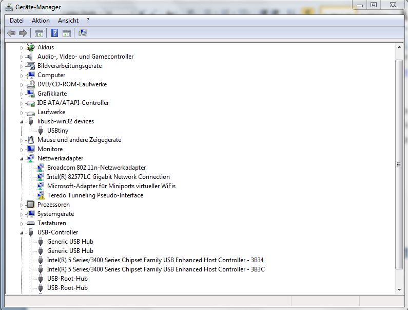
However, it took me a while; the driver was not to be installed. The reason was that I assumed that since the FabISP was now correctly programmed, there must be enough information for the USB. However, when I connected Dan’s FabISB after a while, it was easy to install the USBtiny driver (see image).
Still thinking this must be related to the program, I re-programmed it; soldered SJ1 and SJ2 on my board – edited the makefile to AVRDUDE = avrdude -c usbtiny -p $(DEVICE), (I also set the frequency back to 12MHz), make clean, make hex worked; make fuse failed again – I soldered SJ2 on Dan’s FabISP – make fuse and make program were now successful.
debugging the fab-isp
So great – the FabISP is programmed, however, it still cannot be recognized by the computer, though the USBtiny driver is installed!
Why?
Well, as you can see from the image above, it finally worked: the usbtiny could be recognized and shows up in the device manager. However, I spent some hours in debugging first. Maybe it would have saved some time just making the board again, however, first, you never know how close you are already to find the bug, and second, you definitely want to know about the bug, because what prevents you to make the same mistake again.
First it was interesting that "make fuse" only worked when the SJ2 on the already programmed board was connected? Shouldn’t it work without SJ2 since the two boards are supplied from two USBs now?
The answer is -yes it should, but there are two issues related to that; first, you now know everything is fine from the programming side - coming from the already programmed FabISP and ending at the un-programmed ATtiny44A. However, the USB side is not working, and that means, also not power supply from this side - at least in Windows. So I provided power using an USP-loading device, and since still no power was provided, I found a broken wire bridge, which I had to add to the USB connector since the copper was broken, as the source. Still, the fabisp could not be recognized as USBtiny.
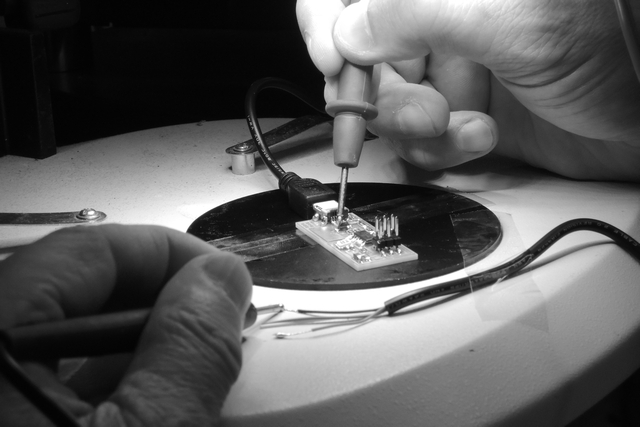
So I used an cut of an USB cable to have access to VCC, GND, T+ and T- and to check the connection from the USB-cable side to the microchip using the diode-testing mode of the voltmeter. The corresponding pins of the microchip a re-soldered to exclude cold-solder-connection, and checked them directly on the free pin of the chip. In addition, I checked the voltages using the USB loading device; all fine, 2.6V at the Zener diodes instead 3.3V as expected, but I cross-checked with the working board from Dan - same voltage. However, what attracted my attention was the voltage on my 20MHz resonator - it was asymmetric - 0.8 vs 0.6V, but it was symmetric on Dan's board, using a 20MHz crystal.
Changing the resonator leaded to success - the voltage is still asymmetric by the way, maybe it was simply broken due to too excessive heat during soldering. A 20MHz signal can be detected at the resonator using the oscilloscope and the USB can be recognized, enabling to the next step.
hello board
- A good start is the respective tutorial.
- Then I downloaded the ftdi-usb driver: VCP-driver*
- Followed by downloading the follwing 3 files from the embedded programming page:
1: the c-file hello.ftdi.44.echo.c
2: the c-file hello.ftdi.44.echo.c.make
3: and the python (py) file "term" term.py
* VCP stands for Virtual COM port - according to the ftdi-page, they "cause the USB device to appear as an additional COM port available to the PC. Application software can access the USB device in the same way as it would access a standard COM port".
hardware checklist
1: connect computer and fabisp board via USB - checked
2: connect computer and button/LED board via USB (black is ground) - checked
3: connect boards together via ISP ribbon cable (double-check ground) - checked
running the programms
now use the terminal to point to the directory containing the hello.ftdi.44.echo files (I put them in the same directory as the firmware-file), and run the following programs:
1: make -f hello.ftdi.44.echo.c.make
2: make -f hello.ftdi.44.echo.c.make program-usbtiny-fuses
3: make -f hello.ftdi.44.echo.c.make program-usbtiny
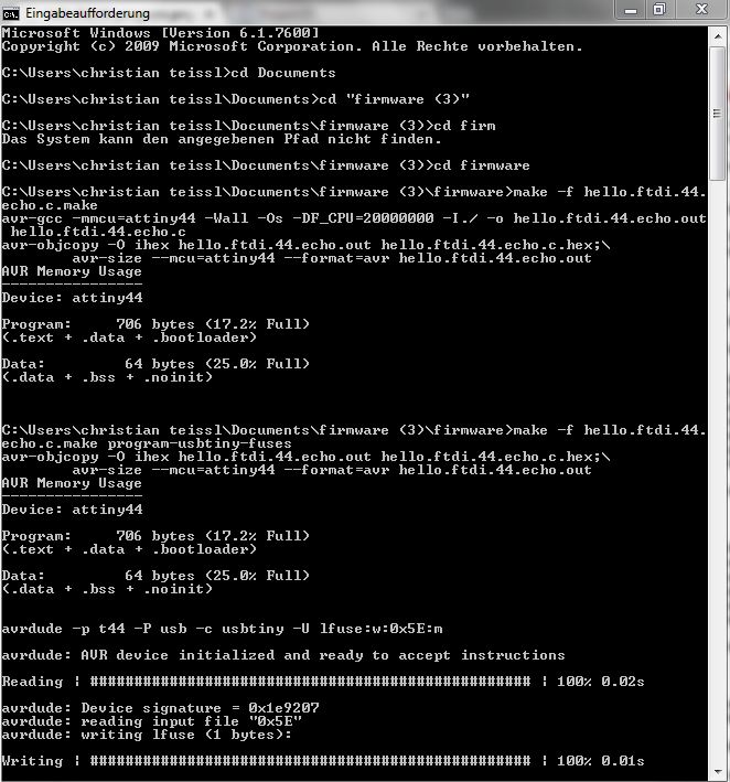
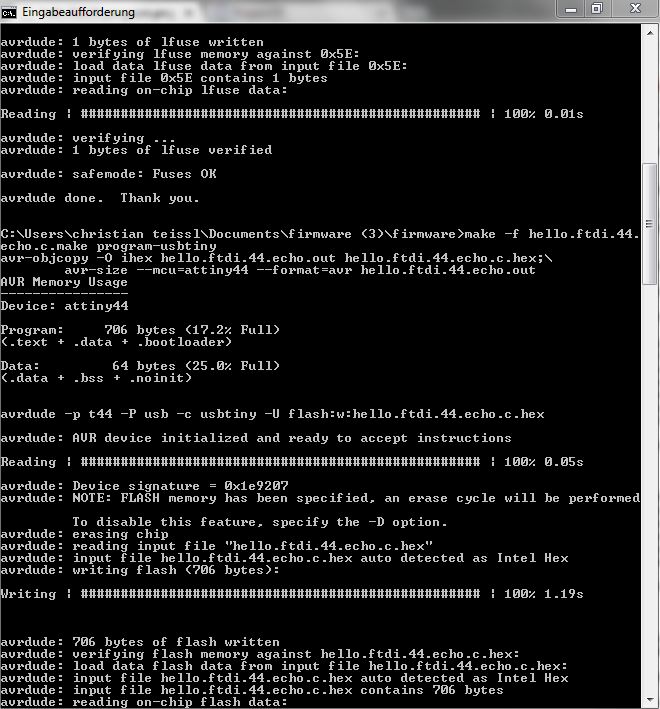
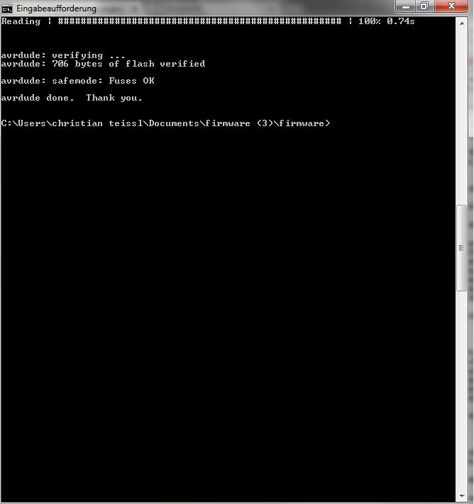
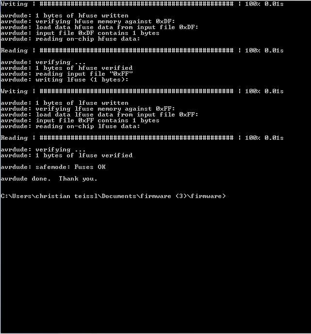
sucessfully programmed!! :-) figure 6 shows the sequence of the terminal messages (you can also find it here). Note that a linked .hex and a .out file have been created.
Now I disconnected the fabisp and left the ftdi-cable connected to the computer.
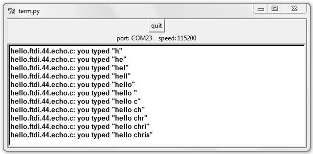
The final step is to run the python application with the appropriate parameters.
- first I had to install pyserial-2.7.win32!
- then I run python term.py COM23 115200 from C:\Python27\, the directory where I put the downloaded term.py file (COM23 is my port, as to be seen from the divice manager, and 115200 stands for the speed);
result: the "term.py" window opened and the hello.ftdi.44.echo.c file and returned the characters "hello chris" which I typed in (see figure 7).
"blink test"
the small c-program
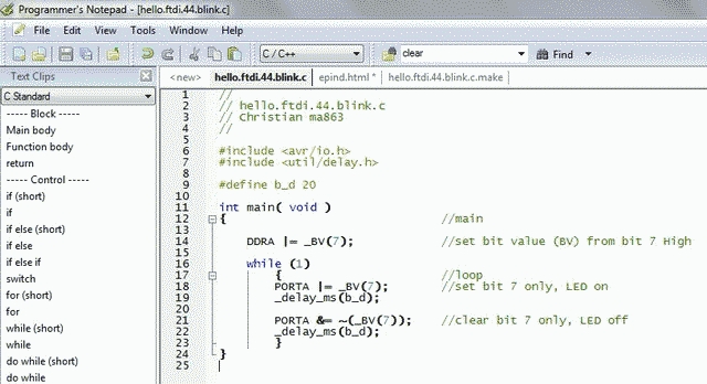
So far so good; it is obvious that not too much is needed to make our board blinking; therefore, When looking at Neil's c-file hello.ftdi.44.echo.c, what do we need and what can we omit for "quick and dirty" a hello.ftdi.44.blink.c program?
- from the header files (extension .h, see "include") we need the input/output, since we want to use the _BV() macro (compiler macro #define _BV( bit ) to set registers;
- and the delay-header file;
if we would like to make it very professional, we could include some additional macros (define), however, for a quick trial we also can do it without and jist build on a single macro without parameters for a delay-constant (d_t). We do not need any sub-program, so only a a short main program remains, as shown in figure 9.
arduino
arduino is an open-source electronics platform (hardware and software). The software can be freely downloaded from the home page. It runs on Windows, Mac OS X, and Linux and is easy to install.
I then had a look at a tour of the arduino internals: how does hello world actually work? from Greg Borenstein, to get a excellent practical introduction into the AVR-chip and its architecture (note that the ATtiny44A we want to program here has only two sets of registers A and B (14 pin layout), whereas in this tutorials 4 registers set A-D are described).It gives a brief intro into the register architecture, I/O (digitalRead/digitalWrite), and the implication in arduino (see below).
The 3 registers adressing each pin are
* Data Direction Register (DDR) - sets the pin-mode to either input or output
* PORT register:if pin is set (configured) by DDR as output, OUT-values are set HIGH (digitalWrite)
* PIN register: if pin is set (configured) by DDR as input, IN-values are registered LOW (digitalRead)
below are some additional handy things good knowing before you start programming in arduino...
* the library functions pinMode has two integer inputs: the pin to be set and the mode (I/O) we want to set this pin (a macro does this internally by using a bit-mask).
* the macro _BV returns the result of shifting the number 1 the given places to the left; e.g., _BV(7) results in 1000 0000 (from 0000 0001).
* the library functions digitalWrite turns on/off a given pin (compare PORT register); note the world digital! This indicates that there is also an lf anaologWrite, which can be used to write out analog values, e.g. to dim an LED or to change the speed of a motor. It does this via Pulse Width Modulation - compare PWD within the libraries and macros - and here also the timer comes into play
* the library functions delay() realizes a time delay in ms using interrupts
* interrups enable event-triggered programming - in the specified event, the program "interrups" and proceeds at a given adress called handler
example: the arduino blink-program
void setup()
{
pinMode(13, OUTPUT); // LED is plugged to pin 13; the DDRx sets this pin as an output
}
void loop()
{
digitalWrite(13, HIGH); // Pin 13 is set HIGH via the PORTx-register
delay(500); // delay of 500ms
digitalWrite(13, LOW); // Pin 13 is set LOW via the PORT-register
delay(500); // delay of 500ms
}