So my computer is sitting there with 5% power left in the battery, and I’m having a crisis deciding what kind of second layer I’m going to draw. Also, I was working too quickly and need to pause for process.
Inspired by electronics kits LED Dice, a die face with seven LEDs and a button, with AT44Tiny sitting on the other side.
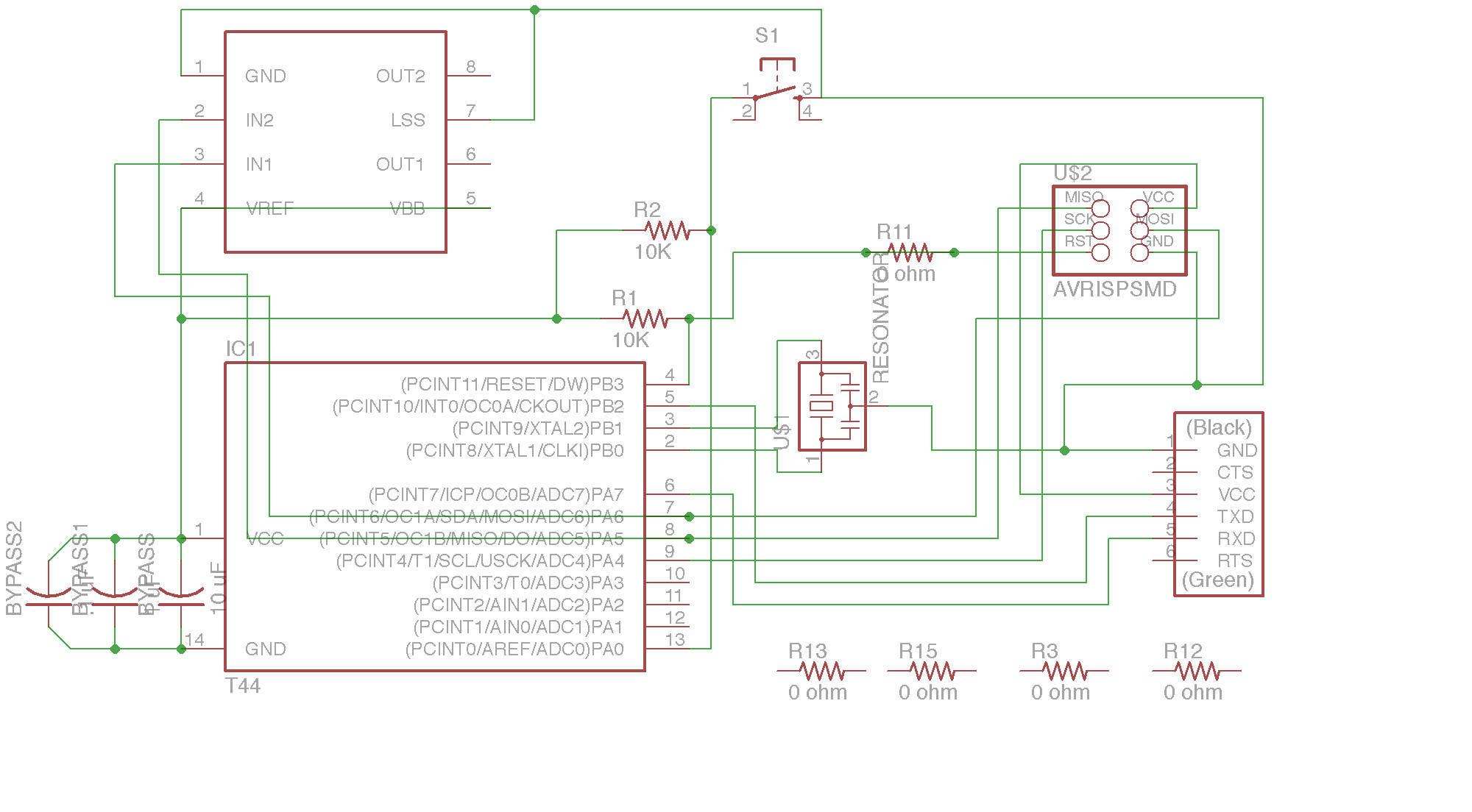
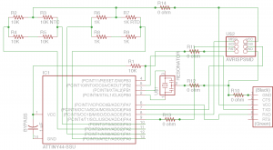
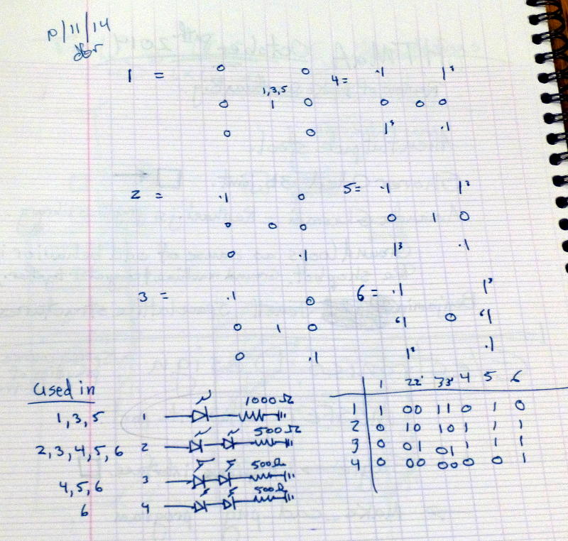
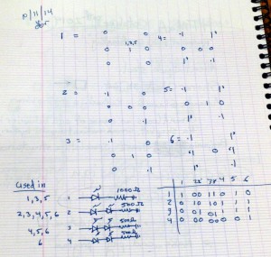 I arranged the LEDs as pips on a six sided die. The truth table on the right shows me I need four digital lines out of theAT44 to drive the display. To keep the LEDs illuminated at the same brightness, I chose initial values of 1KΩ and 500Ω limiting resistors for the one and two LED legs.
If the logical high output is 5V, then 1KΩ passes 5mA to ground. An LED has a voltage drop, so the resistor sees 5V less Wikipedia says 1.8V for red. So the single LED needs a limiting resistor of 3.2V/0.005A, or 640Ω. The two LEDs need a limiting resistor of 1.4V/0.005A, or 280Ω. My guess would have worked at a lower luminance. I was remembering red LED drop as 1.6V.
Also, I was totally thinking, “I have two LEDs, twice the current, half the resistor,” when in fact, the LEDs are in series and share the current. LEDs in parallel are just don’t even. Series and get over the drop in the diode, another reason to go with red LEDs.
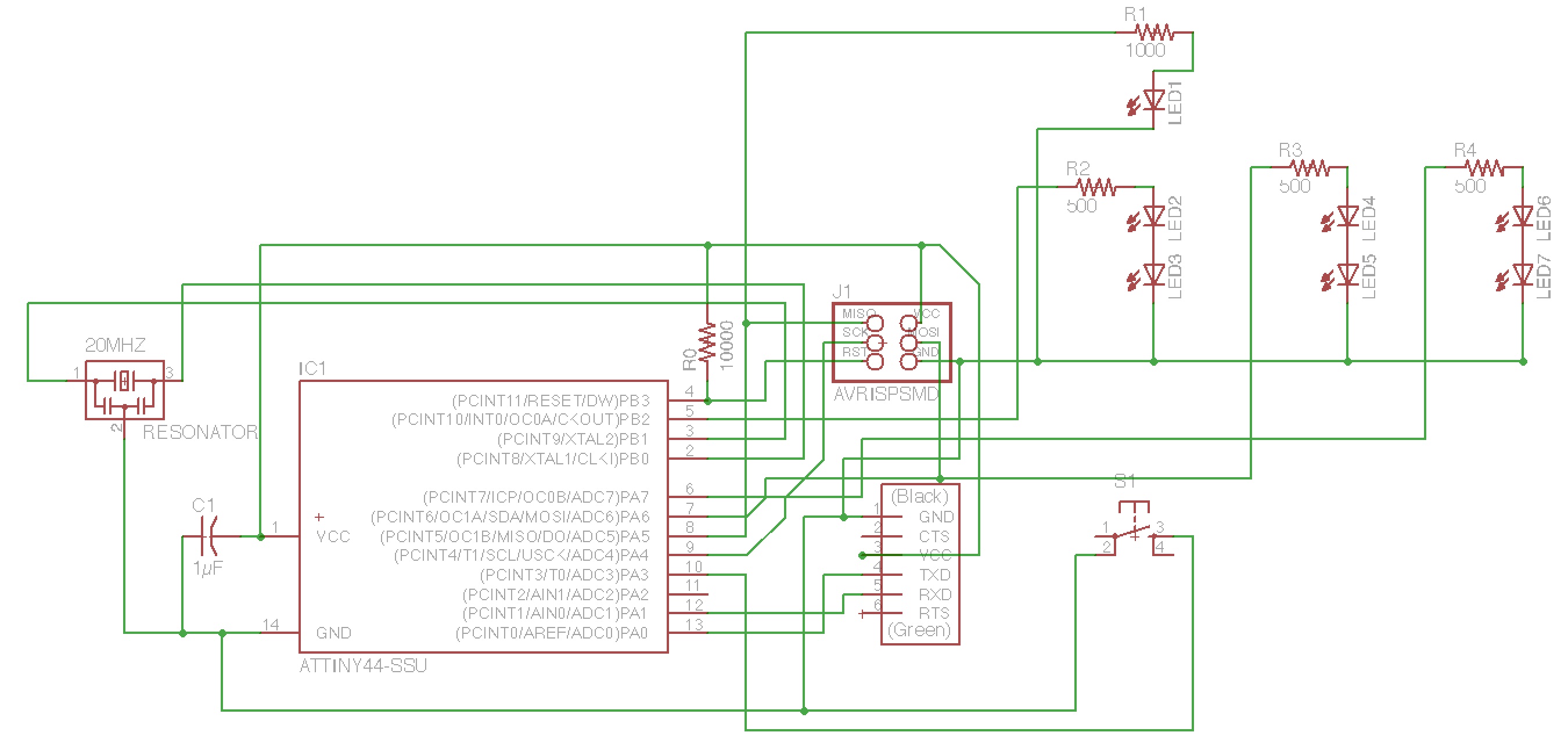
I used Eagle 7.1.0 Light Edition for Mac OS. I included the fab.lbr and ng.lbr component libraries. I was advised to go into the system and create a subdirectory of the /lbr to put most of the other libraries, in order to clean up the interface. In a new schematic file, I placed the required components. My first go used RGB LEDs, which was a lot of space and part. I replaced them with LED1206 and red LED specified.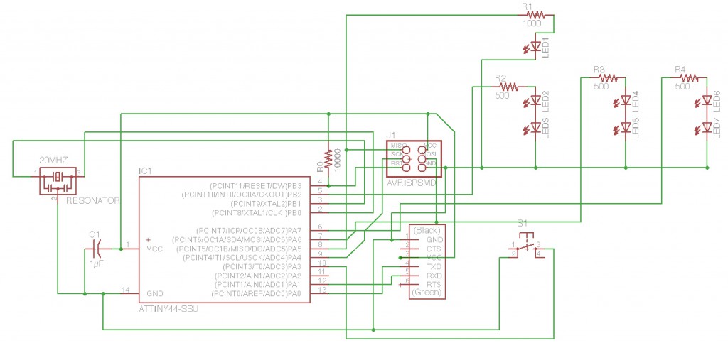
I then used the board command to add the parts and their air wires to a new board file. I used Layer 20 to mark the board out, as a 2″x2″ board with board bottom left set at 0.1″, 0.1″ in the window coordinates, set to 2.2″x2.2″. I placed the LEDs at the corners, sides and middle, keeping the processor, resonator, by-pass cap and reset pull-up resistor together. Many errors in my schematic showed up in the air wires of the board. I went back and used the show command and clicking on nets to make sure connections were where I expected them to be.
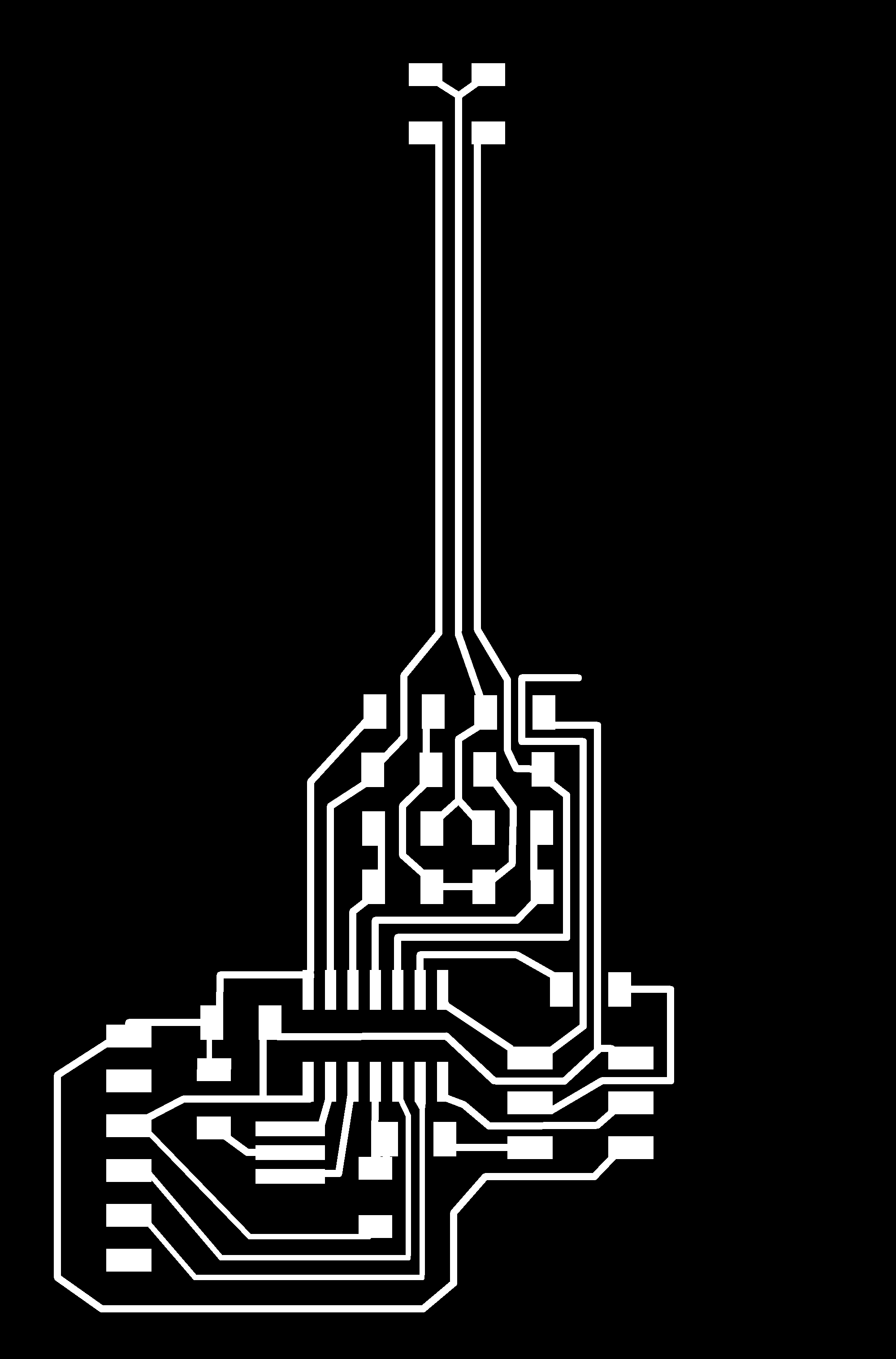
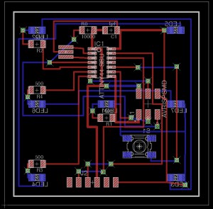 Once all the connections were solid, I routed around, but soon it was obvious that putting the LEDs and switch on one side, and the other components on the other side would give me the room I needed. I used the mirror command to put the LEDs and switch on the bottom Layer 16. Using the route command, drawing from a top layer pad to a bottom layer pad, pause and click at the location for a via, change the layer in the layer dialog box. The wire will chase the cursor. Let it. Choose Layer 16, and then route to the bottom pad.
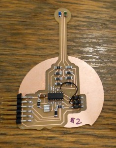
Once I got going with vias, I used them everywhere. Way too many. I cut this board, and it’s almost fully populated, with all the wires in all the vias, soldered both sides. Woof. I already see that my next board has to take advantage of those big 1206 pad spacings and zero Ohm resistors.
I exported the monochrome images of the top and bottom layers, flipping the bottom layer horizontally. I also exported the board outline, which I filled in with white in GIMP to make it the cut out image. The via holes I exported as fine line Xs. I used GIMP to past five pixel wide white spots in the place of the Xs.
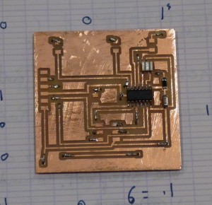 I put three strips of double stick tape across the long of a 4″x6″ double sided board. I zeroed the x and y at the lower left of the board. I zeroed z by dropping the 1/64″ bit. I then ran the fab module, and cut the top layer traces. Next I opened the holes image, and used this as a cut out, changing the logical bit size to 0.1mm to get it to drill the holes. I used the 1/32″ bit for the holes, which made them too big, but still usable. After the holes, I cut out the outline.
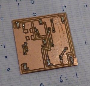
I carefully pried the board up, and after cleaning off the tape, re-taped the front of the board, and replaced it in the cut out space, leaving an even 1/32″ all around. Then I ran the bottom traces file with a 1/64″ bit. The via holes lined up well enough with the bottom layer pads. I used wire and solder to fill the vias.
 Also on the board are the LEDs, which I am not entirely sure I have on there with the right polarity. More components tomorrow.
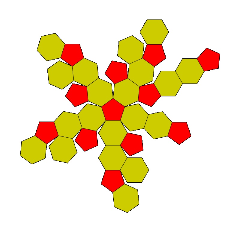
Another design sketch I have uses most of the back of the board as a ground plane, with LEDs and resistors together.
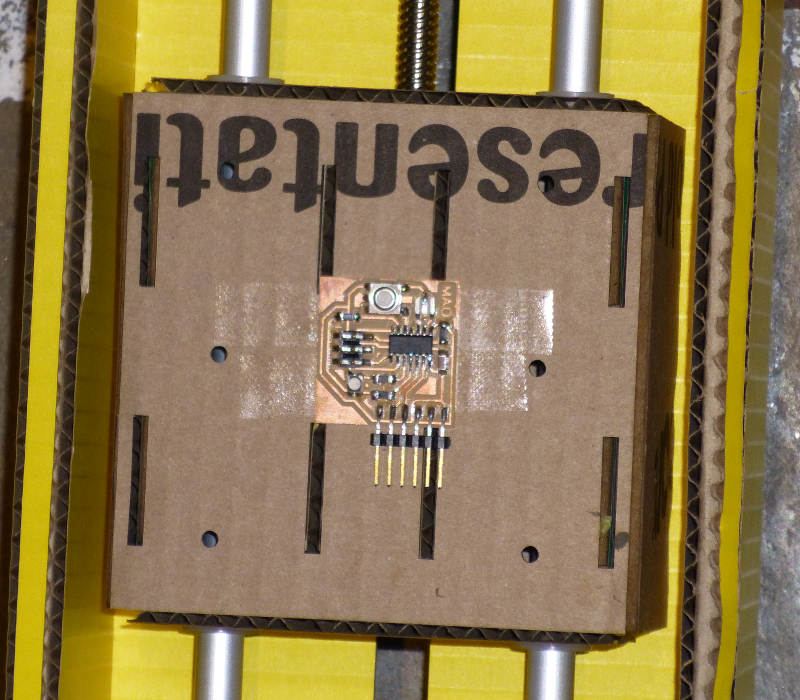
Once the board was assembled, Rob Hart put a quick program on it, which turned all the output lines high, lighting five of my seven LEDs. The diode I switched that morning was the one with the correct polarity, giving me two with the wrong polarity.
I desoldered the two LEDs with a heat gun bearing the nozzle concentrator, as described in lecture. After soldering two more LEDs the right way, I plugged in the board’s power and ground pins to a USB charger break out cable. All seven pips lit red at the same intensity. Hoorah.
I plugged it into a 3.6V lithium cell, and the center pip was brighter than the others, and all were quite dim compared to plugging it into a 6V lead acid battery. All the pips lit at a good 5mA level, visible but not too bright.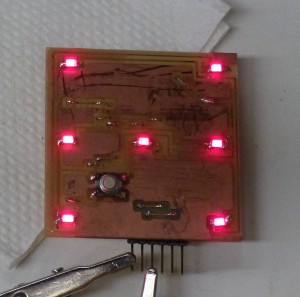
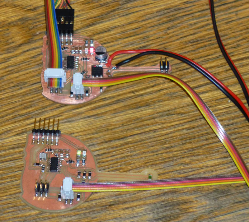
 I cut a new board. Populated and soldered, super careful.
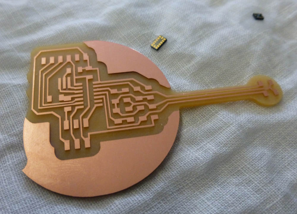
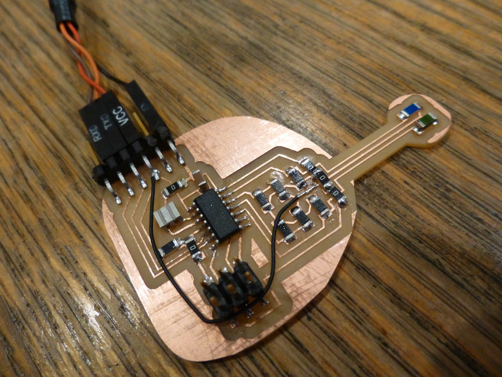
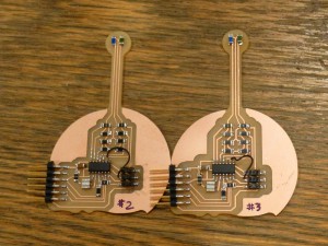 Two boards to compare. Board #3 has thicker leads and wider offsets on the milling.
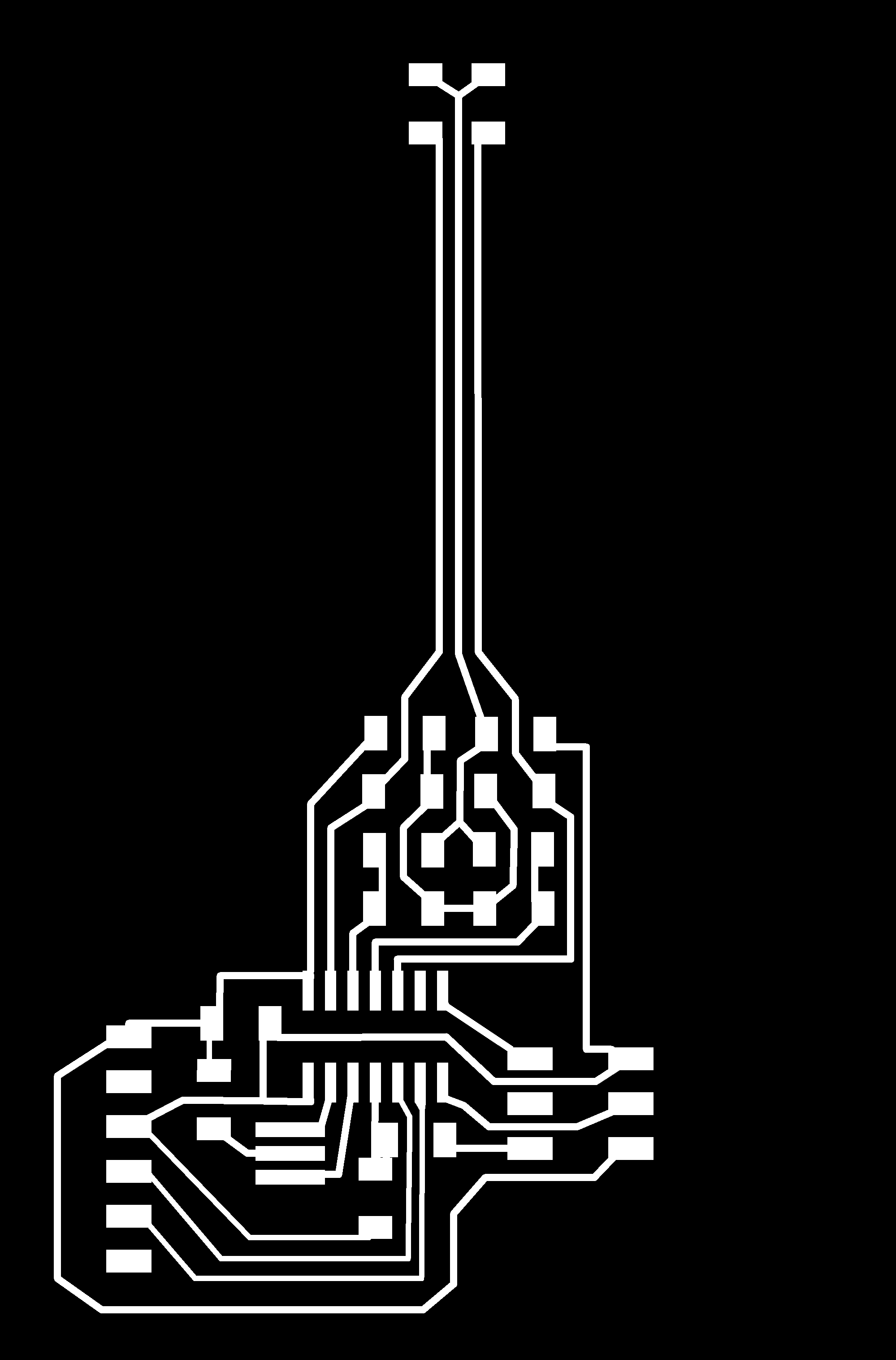
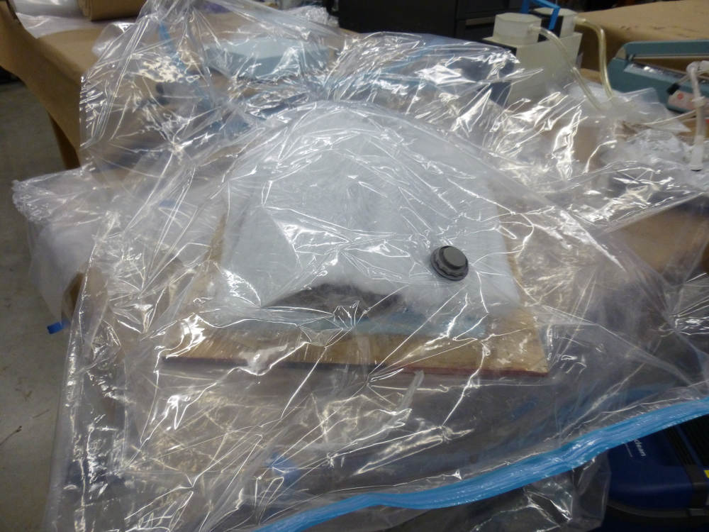
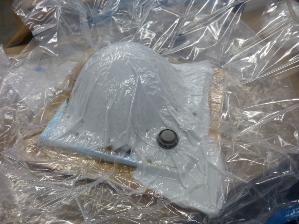
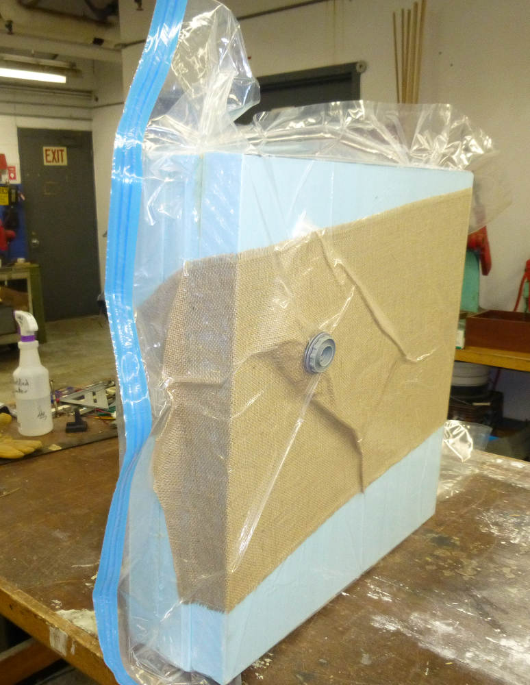
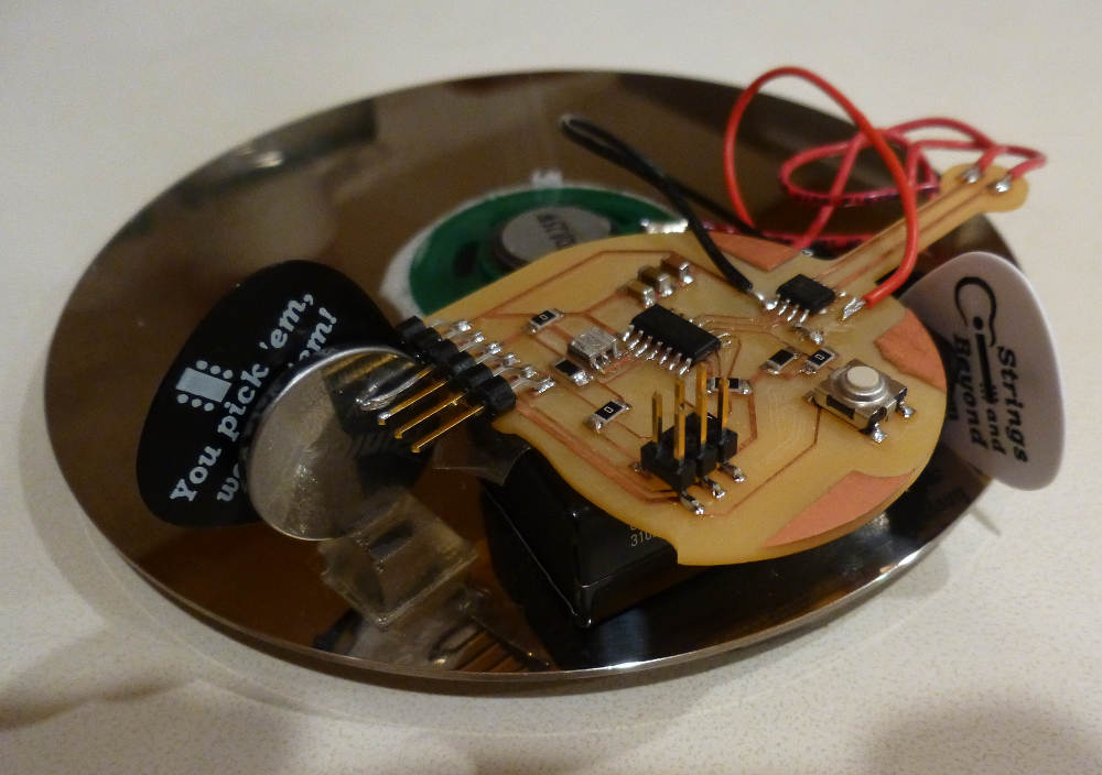
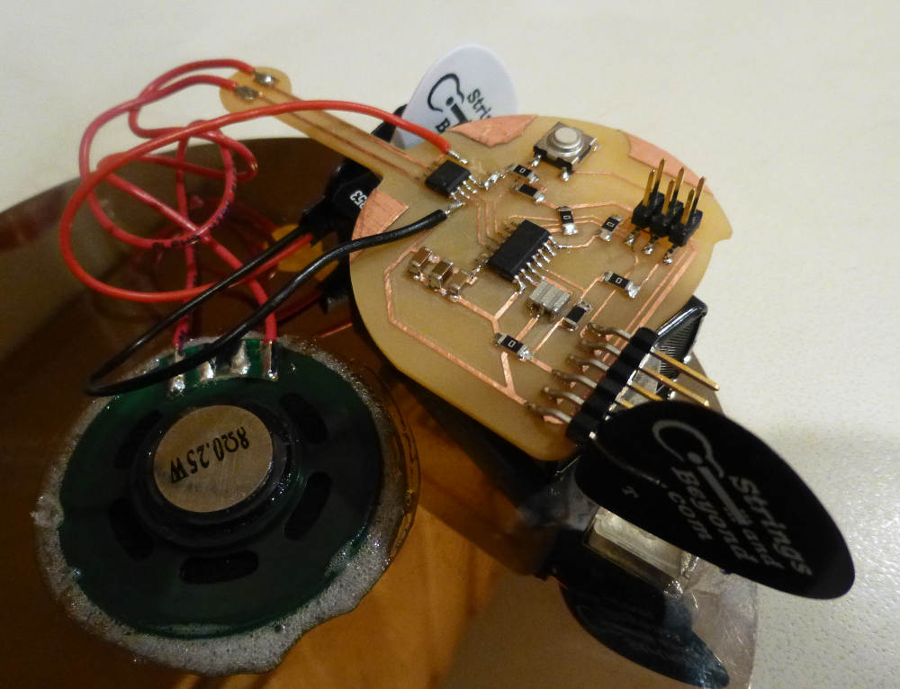
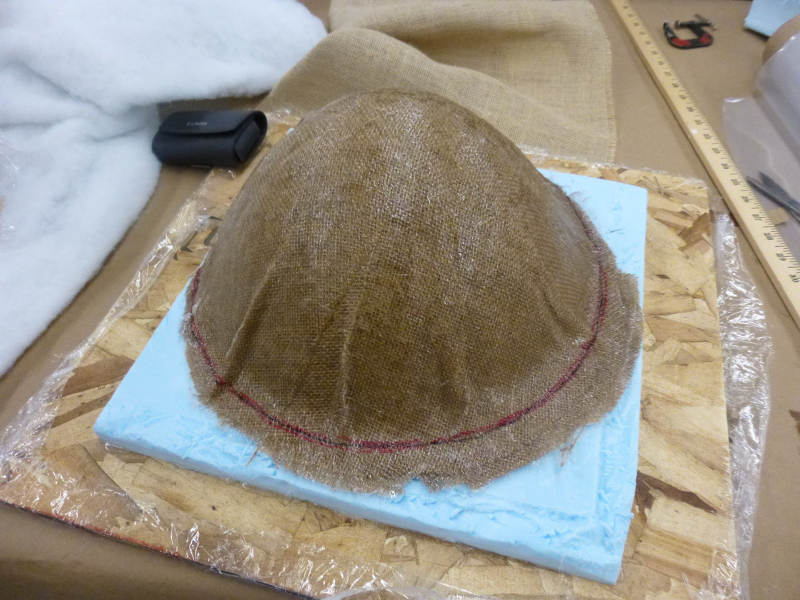
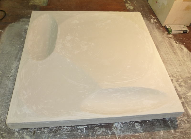
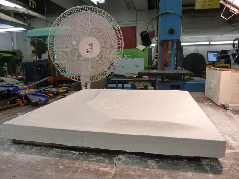
 cured assembly.
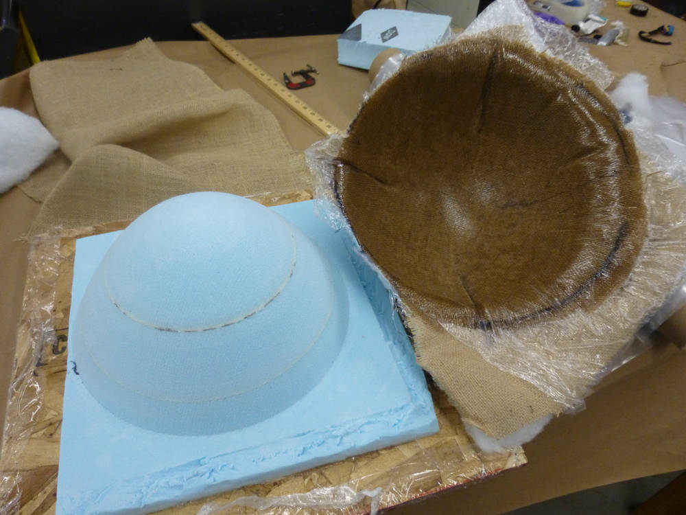
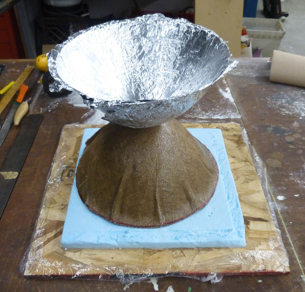
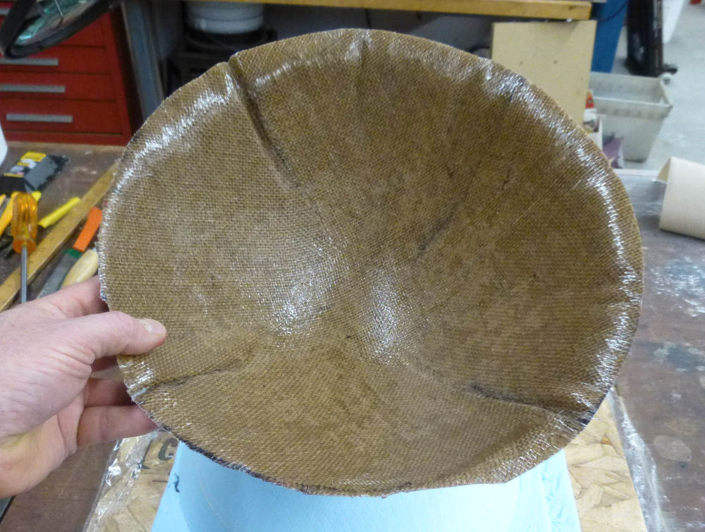


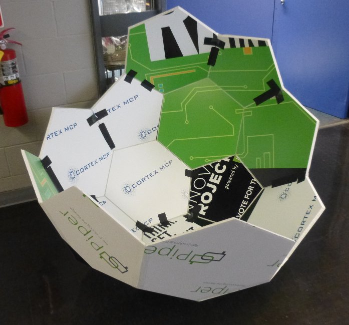
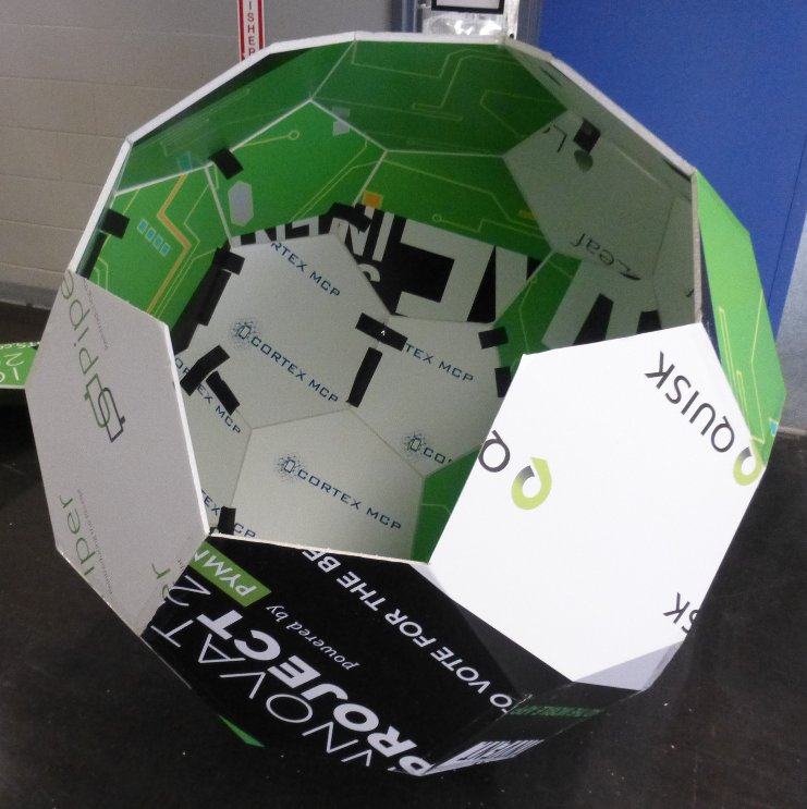
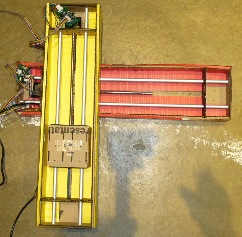
 ts together would take too long. Perhaps assembling the whole, and taking pictures would be the way to go. Taking the parts out into the hallway, assembly with packing tape took about half an hour.