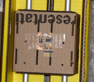
To make the 22 1/8″ long aluminum rails from 72″ stock, on a band saw with a 20″ throat, leave an inch between marked pieces. Cut at a diagonal to fit through the band saw, then trim angled ends leaving 1/8″ fat on rough flat ends. Sand to net and chamfer on a vertical belt sander.
Week Thirteen: Argle bargle bargle.
Process is all I have for this week.
Reading up on ECMAscript. Reading up on Python. Reading python code with a tutorial open. Reading C code, going back over the hello.world examples. Trying to find a level of abstraction I am comfortable with and productive using.
Reading up on the ATmegas and ATXmegas, I really feel like I was lost without a compass. I spent a lot of time in Eagle: editing library packages for the LMNOP44 chip package, connecting pins to components, adding all the extra components necessary for a working board, watching complexity mount to the point of negative return.
My sixth design returns to the ATtinyWE in what feels like defeat. After making the two boards, tempsense and fandrive, and made them talk to the PC, I’m feeling more optimistic.
So much reading and absorbing material with no expectation of getting anything done; in a dazzling moment of clarity, remembering how I was never into programming. But now I keep opening the editor and trying code.
Python versus javascript. If you’ve been there, done that (Python), and have moved over to javascript, it seems a different choice than a beginner might make. I have some experience with software, but I never managed to get the example python code to run. Not a lot of room to mess about with application programming if the interpreter crashes every time it runs because it can’t find some library it needs; was it a bad path, or version mismatch, or the wrong install order? The permutations ate my homework.
Week Twelve: Network Meltdown
Lots of reading up on AVR. Lots of sketching and designing, kibitzing and tangential wandering.
No boards, no network. Designs changing so fast that realization would mean chucking an hour to cut, stuff and solder an unusable board. Nope.
A realization that ArduinoIDE ease of use is not worth the loss of agency, so back to C code and libraries. “Make: AVR Programming” by Elliot Williams hit just the right level for me, in terms of the why’s and how’s of micro-controller coding.
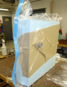
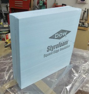
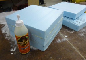
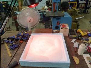
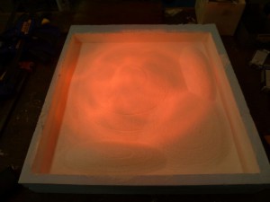
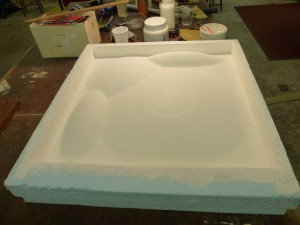
What I made this week was a 6″x24″x24″ block of blue foam using the vacuum garment bag and minimal Gorilla glue. The resulting block rings nicely when struck, suggesting good glue fill and adhesion. That is all.
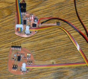
After all that, I was able to connect the two boards together.
Week Eleven: Output
So the thermistor bridge boards from last week will now take a program. So far the values read change on temperature change, but no T in °C yet.
Charles Fracchia suggested a quick detour over into ArduinoIDE and CoolTermMac for communication. Rapid spotty success. Loading Software.Serial takes up 90% of the program memory, yikes.
Lots of use of delays. I guess I should get used to using the microsecond delays, because most of the warnings about settling times are on the order of microseconds. Also turning everything else off. Seems like just setting a bit or two, maybe another control register, let me see…
That was fun.
This week’s project ate last week’s. More to the point, I didn’t hit archive software before major editing, thinking to “save as…” hitting “save” and finding no undo.
Oh my.
I had just gotten to the point where reading the differential channels one way vs. the other gave the same magnitude. The RTD bridge was responsive with 20x gain, while the NTC bridge moves nicely at unity, about the same excursions, 50 units from room temperature to finger temperature, 100 units from room temp. to ice pack. Even without T this will work at ice cream temperatures.
Still not sure about extracting T. Reading about the subject on http://www.omega.com/temperature/z/thertd.html suggests that with four point calibration, 1% accuracy is within reach! Want better? The R/T curve is modeled by a 20th order polynomial. Whee!
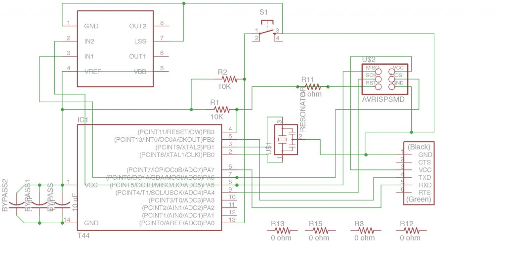
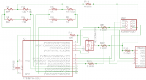
In order to move on to this week’s assignment, I opened up Eagle and got to work. I modified the kTbug schematic after saving it as a new project.
Eagle has a nice way of keeping details in order. The switch is new, and to keep it simple, I put in an external pull-up resistor. Three bypass caps, 10uF, 1uF, and 0.1uF are on the logic side power, and the A4953 H-Bridge calls for 100uF electrolytic and 0.22uF ceramic caps for decoupling the Vbb power. The 9V battery seems to be okay without those, perhaps at this low power, in an application where distortion is a feature.
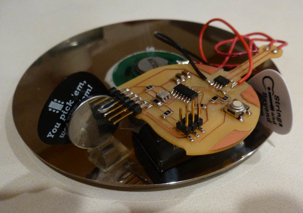
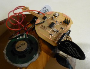
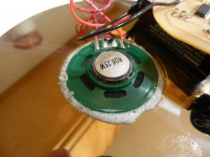
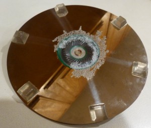
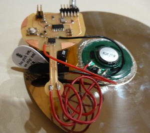
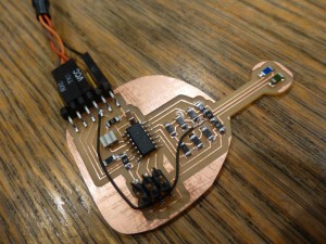
The board is cut, and populated, with the same geometry using the neck to put solder pads at the end. This allowed use of the 1/2″ speaker with spring connectors as a quick test. Here it is shown connected to a 0.25W 8Ω speaker, which is glued (Gorilla) into the hole of a 5 1/4″ HD platter, as a baffle. Small plastic feet hold the platter off the surface, making a resonant volume. Improves coupling of speaker to air, makes louder. Does it boost the high frequencies?
The software is written in ArduinoIDE. It tests for a button push; if the button is pressed, it makes a “pew” sound by PWM in software. If the button is held, six “pews” sound, with an increasing delay between. After six “pews”, if the button is held for three seconds more, five seconds of random noise indicates that the coils have fried.
Things I have learned: The H-Bridge A4953 is boss, but will not work with only Vcc, needs a Vbb, in this case a 9V battery, on a battery clip with leads soldered to Vbb and GND. Then it works hard enough with a 50% duty-cycle to make the speaker coil very hot. PWM tests at low duty cycle first!
I forgot a power switch or two again. The FTDI header makes a nice impromptu battery holder, with a thin guitar pick as a switch. Must learn how to power down the ATt44, or add slide switches anyway.
Some more images:
A video of the first pews:
Week Ten: Input Devices
When my first board did not respond to the ISP, uninitializable, I figured it was a solder problem. I inspected it under the 7X stereo dissecting microscope, no problems in sight. Good looking 1206 components, those thermally sensitive resistors.
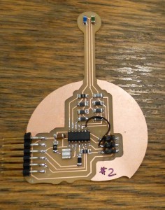
The board extends the thermistor legs of two bridges out away from the rest of the circuit, the head of the bug. An RTD, blue, on the left, and an NTC, green, on the right.
The thorax consists of jumpers and the rest of the resistor bridge, and the abdomen is the ATtiny44A, running at 20MHz with a ceramic resonator.
Why doesn’t the ISP see the board?
Back to Eagle lite software, where by dint of repetition, I began to see the logic of the process, route, rip, repeat. The drawing primitives provided a way to curve the outline layer of the board, and extend the neck of the bug to the limit of the small circuit boards. Group selection and moving involves holding a command key and right clicking, which is non-intuitive and took a while to master. Lucky, I had that time.
I cut a new board. Populated and soldered, super careful.
Didn’t initialize. ISP says Yikes! Actually, AVRDUDE said Yikes, when the return code of the AT44 was #0000000000000000.
Did I overheat the processor? Am I that heavy handed with the soldering iron?
So my process lead me back to Eagle, where I re-routed every line I could to make it a bit more robust. I cut the board, and examined it. I still was not seeing the missing connection.
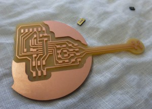
(Above the board is one of the tiny accelerometers, cyanoacrylate glued to a piece of linen, waiting for some 28 ga. wires and solder, perhaps to make a flexible breakout for the part, allowing it to be attached to, say, a violin back under test. It was good practice; I managed to attach five leads.)
A thorough examination of my board, next to a working board, showed me my missing clock connection. I used the fine lead wire to jump the ISP header to the clock pin. And it works.
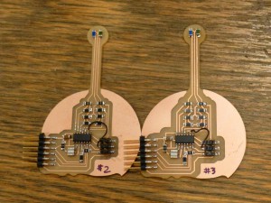
Two boards to compare. Board #3 has thicker leads and wider offsets on the milling.
The most important piece of advice for the Modela: be careful to only have one layer of tape, say two pieces on the long axis of the 2″x3″ board, which extends beyond the edge of the board. Any folds in the tape, or double layers, will throw off the level. Even the raggedy bit of tape at the cut end can be a different thickness, which is why the tape should extend beyond the edges of the board.
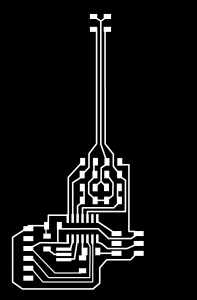
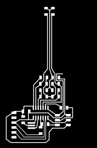
Here is the circuit board trace file. On the left, as cut, with missing lead. On the right, the clock pin is connected to the ISP header with a zero Ohm resistor. For later use, the MISO and MOSI connections are extended out to be available to the right side of the board.
Other lesson of the week: a close examination of the schematic would have saved me some time, but as that time was spent jamming away on Eagle, I count it well spent. I honed the design of the layout several times, learned how to add zero Ohm resistors as jumpers, and tweaked the trace to pad connections for easy cutting.
Other time spent cutting and soldering was equally valuable as practice. Now I have three thermometers.
As for the communication and reading out the temperature, no success with Python talking to the board by FTDI. The code for reading both differential bridge inputs, and comparing the two sets of data, is still in the conceptual stage.
Finally, the extended leads will probably need shielding. My next board will have two copper layers, with the bottom as a ground plane. The whole board will be encapsulated in clear epoxy for use as a voting thermostat input.
Week Nine: Composites
Burlap Epoxy over Foam under Atmosphere
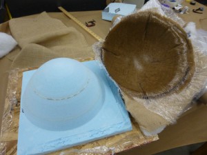
First, make a mold to form the composite. I opted for a one part mold, cut from blue foam. Three blocks of foam, 12″x12″x2″, and Gorilla glue spread on with plastic spreader, sprayed lightly with a mister of distilled water, and clamped with weights. The large block was ready in an hour, and glued to a 14″x14″ sheet of OSB for machining.
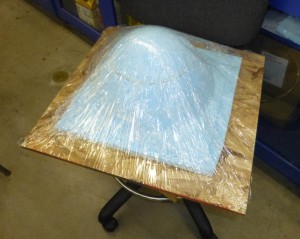
The mesh file was made in Rhinoceros, and is a block with a paraboloid removed. I imported that into PartWorks3D and generated rough and finish cut paths. I used a 1/2″ long end mill for both the rough and finish cuts. The finish cut was made twice, at 45° and 135°. The surface finish was better than the burlap.
Zeroing the machine made it evident that the vacuum attachment would not clear the part. I removed it, and used a shop vac to pick up much of the chaff as it was made. Lots of vacuuming during pauses, and after the machining to clean up the blueness.
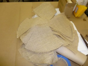
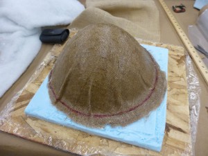
I lay the burlap over the model, made four radial cuts, and marked the darts. I then cut out six pieces of burlap to match. Using Rhino to cut and flatten the mesh, to make a pattern for the burlap: a good idea.
The finished foam model, on board, was wrapped in plastic and sprayed with release agent. Once the epoxy came out, the camera went away, so the mixing of the 24 hour cure epoxy, and pouring and spreading and laying on of layers went quickly and cleanly. Gloves changed three times in the process.
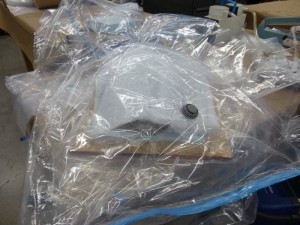
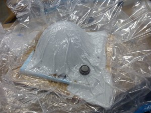
The soaker and breather layer went on, after spray release and rolling punctures. Into the garment bag went the whole assembly, and after a little extra breather layer for the valve, I pulled a vacuum with the HEPA vacuum cleaner. Success. That was easy. Now I’ll put it up on the shelf, *bump* ~sssssssss…
Aw. The board edge cut the bag when I bumped it. The lay up had already splorched the inside of the bag, so I cut the valve and seal off the compromised bag, extended the breather, and placed the whole thing inside another garment vacuum bag, and pulled a vacuum. Success. Super careful now, just fold up the zipper seal ~sssssss. The zipper seal is very sensitive to being moved. Reseal. Re-vacuum. Gently store and back away slowly.
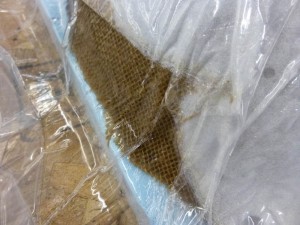
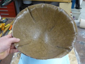
A detail of the burlap epoxy plastic.
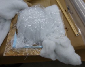
After 24 hours, I opened the bag and removed the cured assembly.
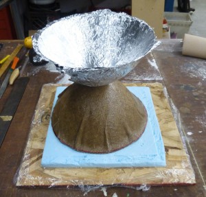
Out popped the shape in burlap epoxy. A little clean up with the band saw, and it’s still a shape. What can I do with this shape? Turn aluminum foil into paraboloids by pressing between the foam and the shell.
Week Eight: Microcontroller Programming
Aw, dang. I programmed the device. Most important lesson: get all of the details right and the tools work and work. One mistake is fail and fail. Commas and semicolons look similar, but oh boy different meanings.
Here I am with copious notes, and a sketchy history of code in several projects. I installed the compiler package for the ARV family of microcontrollers, and XCode, and BBedit’s free version. All of the code was written in XCode. I did not figure out the higher order functions of XCode on macOSX which would, no doubt, have included version control. I read the AT44A data sheet to about 40 pages in, at which point I could see which functionality I could ignore for now. Also I was nodding off.
I made my circuit board from Week Six flash when a button is pressed. Here is the code, brutally unformatted with minimal commenting.
The bit bump OR thingami did not make sense at first, so in order to get logical ones and zeros to the appropriate pins, I wrote a subroutine called showPips() to write all the bits in 0bxxxxxxxx format. I used the same format to write pinwheel(), as a dazzler. Crazy waste of space, which I can tighten up in the next version. However, it works, and is visual.
Bounced around Google looking for a {1..6} random function, which of course was based on rand() in stdlib.h. A subroutine from Yale CS gave me my pseudo-random number, and a counter variable in the main while loop is my dubious source of entropy.
The main() loop uses a while(true) to run, and a counter feeds srand() a seed, and sets a variable to 0 if the switch is pressed. The second while() loop tests for the switch press, and runs a routine if true.
The routine shows 50 random numbers between 0 and 7 very quickly, then settles on value1 {1..6} for a short time. A quick count up from 0 to 7 settles on value2{1..6}. Later code tests the sum of the two values is 7, the pinwheel function is called (not shown in videos).
More work to do: better random seed; program the rest of the game, Craps, onto the board; remake the board for looks and add 2 x CR2016 for power, lose the ISP pins.
Week Seven: 3D modeling and casting
Reaction Coordinate Potential Energy Surface
Foam square. Antimony. Fab Modules. Shop bot. It’s happening…
A marble rolling on a concave surface is subject to an acceleration of (g sin(theta)), something gradient, complicated by something angular momentum with the contact patch offset from the center of gravity. All this results in a trajectory on the surface, and oscillation.
Other potential energy surfaces in the demonstration collection are 1/r of wood, wide and shallow, 1/r of Z-machine plaster finished with epoxy, roughly cubic, and Leonhard-Jones in wood. Models of phase behavior are made of painted plaster. I will be making my mold out of blue foam, and casting it in DryStone plaster.
Starting with a 24″x24″ foam block, I tacked to the surface of the sacrificial layer with hot melt glue. I had the glue gun on hot. A better process would have been to glue the foam to a backing board, with the lower setting on the glue gun to reduce the amount of time waiting for the glue to cool thereby to set and hold. The backing board would then be screwed to the sacrificial layer.
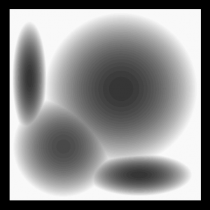
At the encouragement of NG, I downloaded the latest build of Antimony by Matt Keeter. I clicked and dragged until I managed to make a cube((0,0,0),(24,24,2)). With that success under my belt, I proceeded to make spheres to subtract from the cube, now more like a pizza box. Position them parametrically so that they would cut the pizza box cube from above, to 3/8″ of the bottom surface. I adjusted the radius and height to place the spheres in a square arrangement above the box.
Two of the spheres are stretched in the x or y direction, using the deform.scale() function. The smaller round sphere cuts to 1/2″ from the bottom, making it a higher potential energy. I used CSG.difference to remove the sphere volume from the box, and the output shape from each difference as input for the next difference. This might also work by adding all the spheres and subtracting once. I really like Antimony now that I have a sense of how the interface works.
I saved the surface as a height map .png, at the highest resolution. Upon reflection, the frame around the image is redundant, adding to the machining time by cutting air.
The first board I cut I used the software supplied with the ShopBot, and started the roughing cut. The depth was too large, and if finished would cut through the board. Remembering the fab modules, I stopped the cut, and re-calculated both cut paths. The PartsWorks3D cut path had already removed some high spots, so after a short while I stopped the job, replaced the foam, and started over.
The rough cut was made with a long 1/2″ bit, and the cut path by the fab module was 1/16″ lower than the eventual finish cut, which was made with a 1/8″ long ball end mill. The overlap was 50%, which is too little for a cut like this, even with the diagonal cross pattern.
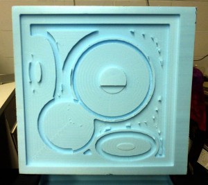
The finished foam after cutting. The ding on the small round was the result of dropping the 1/2″ bit when removing it after the rough cut.
The next step involved gesso, three coats of regular, then three coats of hard gesso, with sanding in between applications. Another approach which I considered as I waited for the gesso to dry, was to cut the form with higher rough cut, and a higher resolution fine cut, followed by application of hot air from a heat gun on medium.
I experimented with scrap foam and the heat gun, and found that the surface did not slump as quickly as I expected. The shiny, heat sealed surface would make a nice mold. I will leave that for the next iteration of the model.
A close-up of the surface with the first coat of gesso. The cross hatching is visible, as well as the remains of the rough cut.
The drying time was hastened by adding a fan and a heat lamp to the work area.
The last coat of hard gesso was sanded and the dust removed, and a layer of wax applied as a mold release agent.
Finally, I mixed up a big batch of DryStone plaster, and filled the mold. I didn’t take any pictures, because I was busy dealing with the overflow and mess. No time, and no desire to wreck the camera. Waiting for the plaster to set gave me the time to mop up the place. When the plaster was set and getting hot, I inverted the mold, flexed the sides a bit, and popped out the piece.
Cooling the piece, per instructions on the package.
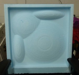
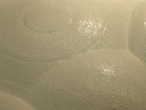
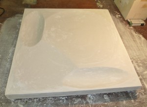
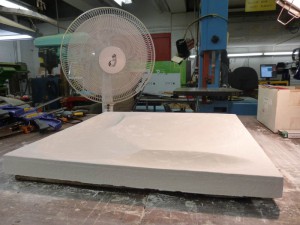
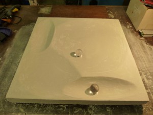
Testing the surface with plexiglas spheres, and below are two videos of the spheres rolling on the surface.
fin
Week Six: Modify a Microcontroller
So my computer is sitting there with 5% power left in the battery, and I’m having a crisis deciding what kind of second layer I’m going to draw. Also, I was working too quickly and need to pause for process.
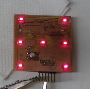
Inspired by electronics kits LED Dice, a die face with seven LEDs and a button, with AT44Tiny sitting on the other side.
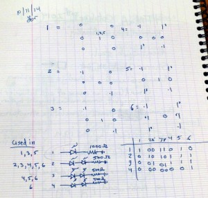
I arranged the LEDs as pips on a six sided die. The truth table on the right shows me I need four digital lines out of theAT44 to drive the display. To keep the LEDs illuminated at the same brightness, I chose initial values of 1KΩ and 500Ω limiting resistors for the one and two LED legs.
If the logical high output is 5V, then 1KΩ passes 5mA to ground. An LED has a voltage drop, so the resistor sees 5V less Wikipedia says 1.8V for red. So the single LED needs a limiting resistor of 3.2V/0.005A, or 640Ω. The two LEDs need a limiting resistor of 1.4V/0.005A, or 280Ω. My guess would have worked at a lower luminance. I was remembering red LED drop as 1.6V.
Also, I was totally thinking, “I have two LEDs, twice the current, half the resistor,” when in fact, the LEDs are in series and share the current. LEDs in parallel are just don’t even. Series and get over the drop in the diode, another reason to go with red LEDs.
I used Eagle 7.1.0 Light Edition for Mac OS. I included the fab.lbr and ng.lbr component libraries. I was advised to go into the system and create a subdirectory of the /lbr to put most of the other libraries, in order to clean up the interface. In a new schematic file, I placed the required components. My first go used RGB LEDs, which was a lot of space and part. I replaced them with LED1206 and red LED specified.
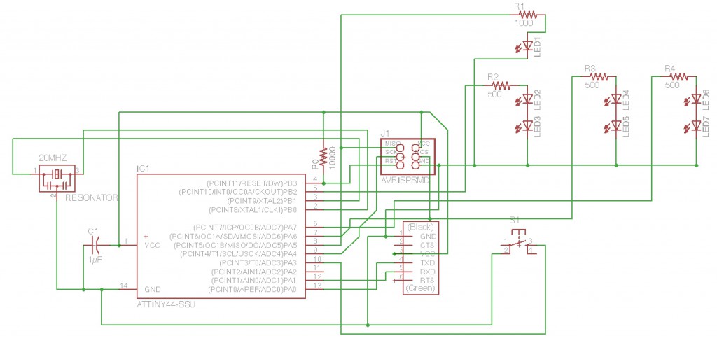
I then used the board command to add the parts and their air wires to a new board file. I used Layer 20 to mark the board out, as a 2″x2″ board with board bottom left set at 0.1″, 0.1″ in the window coordinates, set to 2.2″x2.2″. I placed the LEDs at the corners, sides and middle, keeping the processor, resonator, by-pass cap and reset pull-up resistor together. Many errors in my schematic showed up in the air wires of the board. I went back and used the show command and clicking on nets to make sure connections were where I expected them to be.
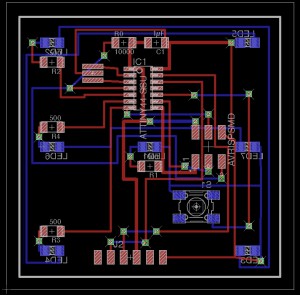
Once all the connections were solid, I routed around, but soon it was obvious that putting the LEDs and switch on one side, and the other components on the other side would give me the room I needed. I used the mirror command to put the LEDs and switch on the bottom Layer 16. Using the route command, drawing from a top layer pad to a bottom layer pad, pause and click at the location for a via, change the layer in the layer dialog box. The wire will chase the cursor. Let it. Choose Layer 16, and then route to the bottom pad.
Once I got going with vias, I used them everywhere. Way too many. I cut this board, and it’s almost fully populated, with all the wires in all the vias, soldered both sides. Woof. I already see that my next board has to take advantage of those big 1206 pad spacings and zero Ohm resistors.
I exported the monochrome images of the top and bottom layers, flipping the bottom layer horizontally. I also exported the board outline, which I filled in with white in GIMP to make it the cut out image. The via holes I exported as fine line Xs. I used GIMP to past five pixel wide white spots in the place of the Xs.
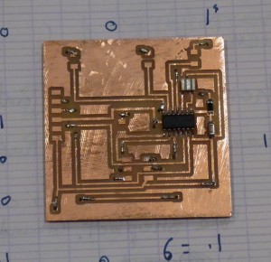
I put three strips of double stick tape across the long of a 4″x6″ double sided board. I zeroed the x and y at the lower left of the board. I zeroed z by dropping the 1/64″ bit. I then ran the fab module, and cut the top layer traces. Next I opened the holes image, and used this as a cut out, changing the logical bit size to 0.1mm to get it to drill the holes. I used the 1/32″ bit for the holes, which made them too big, but still usable. After the holes, I cut out the outline.
I carefully pried the board up, and after cleaning off the tape, re-taped the front of the board, and replaced it in the cut out space, leaving an even 1/32″ all around. Then I ran the bottom traces file with a 1/64″ bit. The via holes lined up well enough with the bottom layer pads. I used wire and solder to fill the vias.
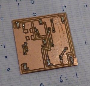
Also on the board are the LEDs, which I am not entirely sure I have on there with the right polarity. More components tomorrow.
Another design sketch I have uses most of the back of the board as a ground plane, with LEDs and resistors together.
Once the board was assembled, Rob Hart put a quick program on it, which turned all the output lines high, lighting five of my seven LEDs. The diode I switched that morning was the one with the correct polarity, giving me two with the wrong polarity.
I desoldered the two LEDs with a heat gun bearing the nozzle concentrator, as described in lecture. After soldering two more LEDs the right way, I plugged in the board’s power and ground pins to a USB charger break out cable. All seven pips lit red at the same intensity. Hoorah.
I plugged it into a 3.6V lithium cell, and the center pip was brighter than the others, and all were quite dim compared to plugging it into a 6V lead acid battery. All the pips lit at a good 5mA level, visible but not too bright.
Week Five: Make Something Big
This week I’ve been watching and helping others use the ShopBot more than using it myself. The experience leads me to eschew the OSB in favor of foam core board.
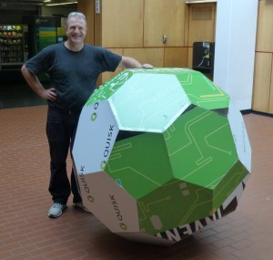
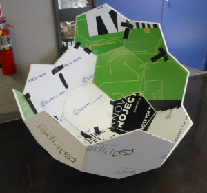
A recent conference left scores of 1/2″ thick 5’x8′ foam core boards, some ten of which were saved as stock. The ShopBot Buddy can cut a 4’x4′ piece, so I used that as my size limit for making a truncated icosahedron, or soccer ball shape.
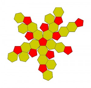
I downloaded an unfolded net of the shape from http://en.wikipedia.org/wiki/Truncated_icosahedron, with an eye to identifying the subsets of faces to cut from my board.
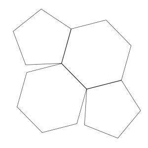
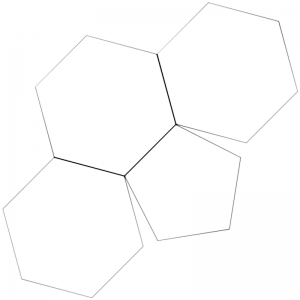
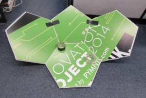
The truncated icosahedron is made of 20 hexagons and 12 pentagons. These can be divided evenly into four sets of 5 hexagons and 3 pentagons, but the shape would be too small if each of the sets was cut from a 4’x4′ board. Dividing further makes for two different sets, one with 3 hexagons and 1 pentagon, and one with 2 hexagons and 2 pentagons.
I made the shapes in Inkscape, and scaled them so the larger (3,1) shape just fit on the 4’x4′ sheet. I also traced the outline to make a cut-out path.
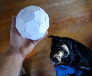
As a test, I printed out four of each of the shapes at 9% on paper, cut out the shapes and taped them together into a little version. Doge is not convinced, but it looks good to me.
With a mat knife, I cut the large foam core sheets into 4’x4’s. I used nine gaffer tape loops at the corners, sides, and center, to hold the sheet to the sacrificial layer.
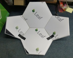
The boards have a green side and a white side, which I used for the outsides of shape (2,2) and shape (3,1) respectively. For cutting, the outside is taped down to the sacrificial layer, so I took care to coordinate color with cut list.
The bit was the 1/2″ 60° V at 12,000 rpm and a feed rate of 4″/sec. The first cut was an outline of all the shapes at a depth of 0.450″, and the second cut was the silhouette of the shape at 0.525″, just outside the line. The cut through was only successful on one of the eight boards, leaving me to cut out the shapes with the mat knife.
Once all the pieces were cut, I began to tape them into 3D forms.
Pulling the sides together on the inside with gaffer tape made the 3D shape, and clear packing tape on the outside seams held them securely.
I taped all of the parts and stacked them, with the thought that I would carry all eight pieces to class and assemble them there.
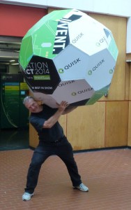
A quick assembly test made it clear that putting eight parts together would take too long. Perhaps assembling the whole, and taking pictures would be the way to go. Taking the parts out into the hallway, assembly with packing tape took about half an hour.
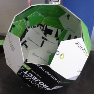
My plan to bring it to class involves cutting the finished object into two equal segments which will fit in a van, and an elevator. Once in the classroom, the segments will be taped together to make the big truncated icosahedron.