Final Project
Work on Project
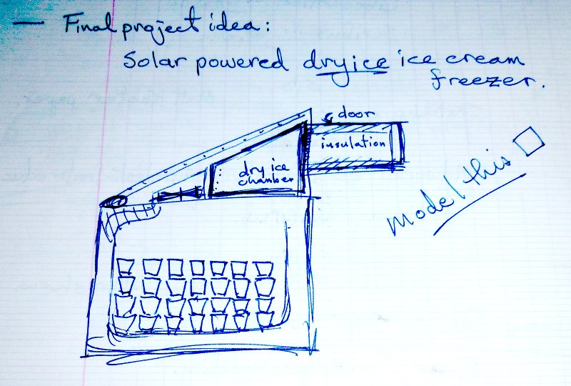
12/3/2014 Proposed final project is a thermostatic dry ice freezer.
Searching Google for “dry ice freezer” brings up alibaba.com, where in a stack of water ice makers and dry ice makers, the Zhengzhou Dison Electric Company, Ltd is selling Portable-dry-ice-freezer-Exact-temperature cooler. The cooler weighs 65 kg net for an 80 liter/80 kg cargo, and uses 30 kg of dry ice. This 175 kg portable cooler was available online for $4,580 with free shipping.
Search for “dry ice” and dryiceinfo.com is high on the list. Practical and funny and useful, with safe handling emphasized. When suggesting that unneeded dry ice be thrown into a sink garbage disposal with running hot water to “make a marvelous eruption,” the author has us wear safety glasses and stand back. Safe use of dry ice as a refrigerant requires venting and good ventilation. Dry ice in a standard freezer will shut down the thermostat; don’t do it! Unless the electricity is out, in which case, do it carefully; instructions included on site.
The use of dry ice to keep stuff cold is called Total Loss Refrigeration. The simplest form is to pack the top and bottom of a styrofoam cooler with dry ice, with the frozen product between. This works for shipping, but has the drawback of cooling the product way below serving temperature.
Dry ice sublimes at ~-80°C. The enthalpy of sublimation of carbon dioxide is 571kJ/kg, with a density of 1.4-1.6 g/cm3. A foam lab bucket holds about 4kg of dry ice pellets, losing about 3kg over 24 hours. The foam is about 3/4″ thick flexible polyurethane.
Use an actual cooler or make something? How would it work in a beer cooler? The dimensions of my square in a rectangle representation are 1’x1′ in 2’x3′, or 12 cu.ft. That’s big. A cubic foot of dry ice is 90#, so a tenth of that for this device. Next step is to make a box in Rhino, and choose a fan size.
Fan chosen is 120 x 120 x 24 mm, drawing 0.53A at 12V. The box is designed out of 2″ blue foam.
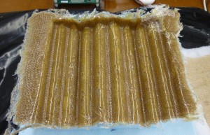
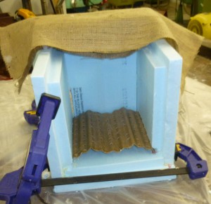
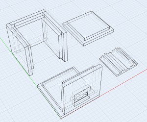 The box is made up of a bottom, a top, three identical sides, and one side with a fan cut-out. The parts are ship-lapped for one side machinability. The curve extrusion is a form for a burlap/epoxy composite to fit in the bottom of the box as a plenum.
Thanks to David Robert for help with 3D modeling and programming work flow.
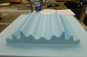 On Friday: Cut the plenum form. Mixed up the 4hr epoxy and applied three layers of epoxy soaked burlap to the mold-release-covered form.($3) Covered with breather and soaker layers, and placed into a garment vacuum bag. ($2) After three hours otherwise spent as shop buddy and working on this web site, I had to go, so I checked if the epoxy was cured enough to demold, which it was.
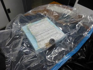 The vacuum bag was leak free. I took extra care to have a barrier layer between the bag and the lab table or other surfaces, to avoid accidental nicks. Large trash bags work well, here a bin liner.
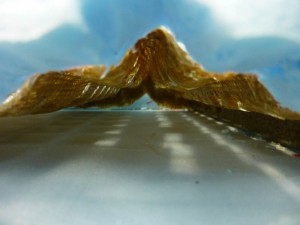
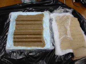
The breather layer separated cleanly, and the part pulled off the form easily. It appears from the underside of the part that the epoxy pooled in the deep concavities of the form. One solution would be to make the form shallower. A quicker fix might be to use a piece of burlap under the plastic, next to the foam. I did not use it on this piece because I hoped to get those deep curves. Since I lost the resolution anyway, a layer of burlap would act to reduce the volume of un-reinforced epoxy.
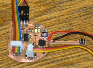
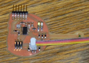
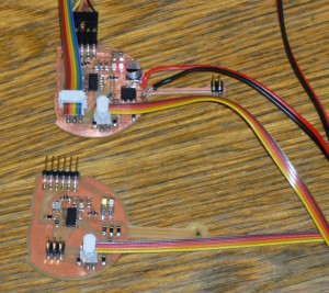
Also on Friday, I got both of the circuit boards communicating with the serial terminal, making use of the serial comm code in the hello.echo example.
I had to modify the #defines to specify serial_port_in and serial_port_out, because the pins I chose on the ATtiny44 for RX and TX are on different PORTx.
After checking that both boards ran the hello.echo example, I began to write specific software for each. As a first round, the tempsense board reports the ADCL and ADCH values, thanks to the hello.temp examples. The fandrive board counts from 0x00 to 0xFF.
On Saturday, I defined another pair of pins for the board-to-board communication, implemented on the pair of pins which, on another loop of the development spiral, will act as an I2C port.
Now, my next goal is to have the tempsense board tell the fandrive board to turn on a fan.
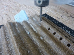 I used VCarve software to generate a square pattern of 1/4″ holes in an 8″ grid, with the piece gaffer taped to the board, and a foam block to support the middle of the open end. Drilled and trimmed, the plenum fits in the box. But I get ahead of myself.
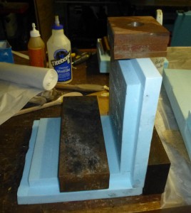
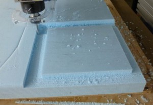 To make the box parts, I glued a piece of blue foam to a backing board, and loaded the .dwg 3D file into PartsWork3D. I calculated a rough path and a finish path, and an hour later, I had one side panel. The finish was rough.
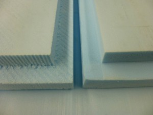
No way to make these parts on the shopbot in time. Since I designed the sides of the cube to ship lap together with only one side machined, I chose to cut the pieces quickly and cleanly on the table saw. Once the four 11″ and two 12″ squares were cut, I set the saw blade height to 1″, the fence to 1″ minus the saw kerf. Running each square through flat, all four sides, then vertical to the fence to remove the rabbet. Overall about 20 minutes of work.
I then set about to glue the sides together. First, one side is glued to the bottom, and two other sides are glued together. It was late Saturday night, and I was singing, “Another Saturday night, and I got my ShopBuddy.
I got a project and it must get made.
How I wish I had something to show for,
all of the boards I made.” So I left the parts to cure.
On Sunday: I just wired the fandrive board with a 12V power supply on the NMOS-FET I am using as a power switch. On/Off. There are fans with a third wire which allows for PWM control of the speed. That is on a higher loop of the spiral, as it would involve a board re-design. It would allow for a three pin header on the board which would connect to both 2 and 3 wire cooler fans.
I just wrote a two second toggle for the fan pin, and the fan barely twitches. A voltmeter shows the source voltage switching between 3.3V and 0.3V, which seem very odd given the open-circuit voltage of the wall-wart I’m using is 19V. Could this be the wrong part? Is there a 3.3V regulator chip with the same package? oh, my. No. I’m using the NMOS the wrong way, and I can’t drive a drain at 12V with a 5V gate. 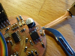
Back to Eagle, where a few minutes of modification put the fan between the 12V and the mosfet, and retouch the board, and that should work. Now, is there any way I can hack the board I have to make those connections? Ha ha! Yes. A little cut here, a little blob of solder there. Don’t forget to account for cut ground connections. Solder the 12V wall-wart 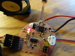 wires into their new places, plug it in, power on the board, and there goes the fan, whooOOoo…… whooOOoo……. whooOOoo…… as it powers on and off every two seconds.
On Monday: I glued together the two partially assembled parts of the foam cooler into three sides and the bottom. To fit the plenum piece, I cut a wedge out of the base of the side walls. The piece then slides right in. By pressing the fourth wall into place, the edge of the composite marks the inside for cutout.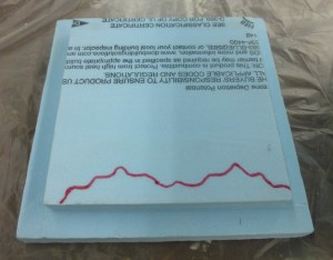
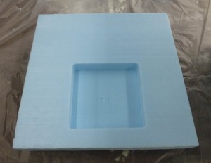
The fourth side of the box needs a cut out for a fan, so I taped it down on the shopbot bed, created a toolpath in VCarve software, and cut it out. The 1/2″ bit at 12000 RPM left a smooth finish, and the correct radius for the fan corners as a bonus.
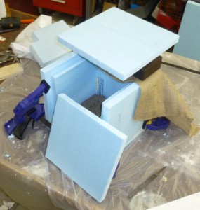
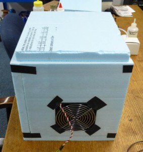
With the fourth side cut for fan and plenum, it is time to assemble the box. I’m going to leave it taped for the time being. The fan fits.
A pin header soldered to the output wires lets me plug the fan in, and the fandrive board runs the fan on a four second cycle, to test the mosfet and power supply.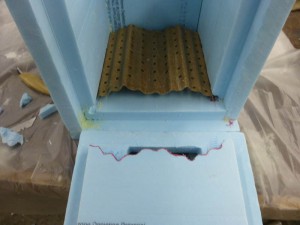
Code written for the tempsense module.
Code written for the fandrive module, above link also, down at the bottom.
