Week Four: 3D Scanning and Printing

3D Scanning

3D scanning with the Sense from Cubify was strangely primitive, like whacking at the problem with a silicon axe. Technique matters.

My model is a grifola frondosa mushroom, found in the woods.

Hen of the woods mushroom on forest floor.

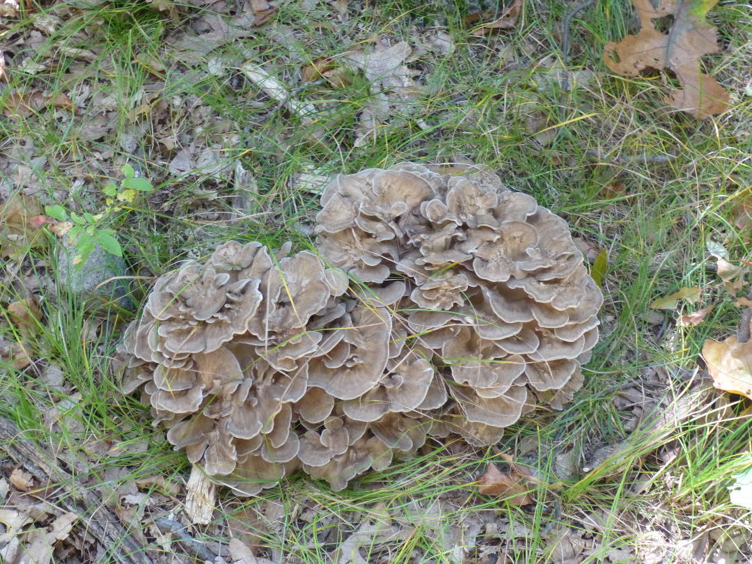
I scanned two mushrooms with the small object setting, on a stage made of cork board and black velvet. The proprietary software is easy to use. Once the choice of object is made, a live preview window opens. The space bar starts a three second timer, and then capture is live.

Maintaining line of sight with the object in the cross hairs felt awkward, with the alignment of monitor and stage always off at some part of the scan. Perhaps practice would enable scanning without constant reference to the screen for alignment.

After a few failures due to loss of alignment, I succeeded in making a scan. I tried to re-align the Sense, but with no luck. My conclusion: if you lose alignment, bail by hitting the home button, and start again.

I saved the scan as both .stl and .obj files. The .obj contains the color information, while the .stl is just the mesh. Ah, the mesh. 149,316 vertices, 282,688 polygons.

I trimmed the mesh to remove the stage, leaving only the mushroom.stl.

Screen capture from Rhino.

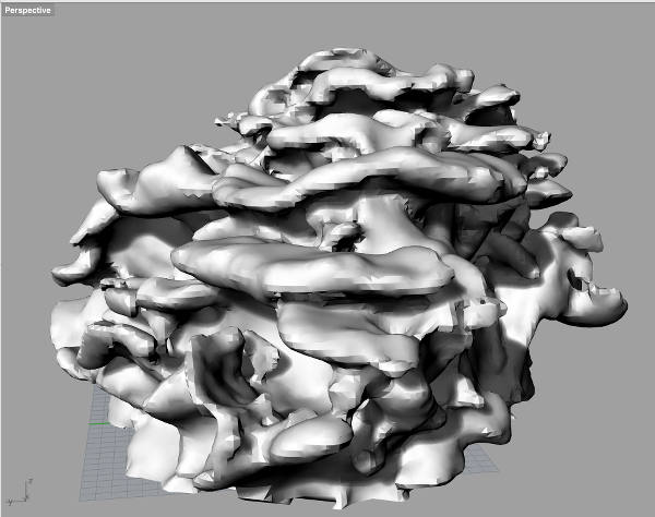
The trimmed mesh still has roughly 100,000 vertices and polygons, 10 megabytes, and handily crashes Cura.

The latest edit is here, down to 1.5MB and 14,000 vertices. Right click and save linked file to look at the
 mesh file.

3D Printing

I chose Rhinoceros as my 3D modeling software.

The object I designed is a sphere with helical voids arranged tetrahedrally, so that springs can be glued between the spheres, producing a lattice in either the ice or diamond crystal pattern.

I spent long hours trying out the various commands, and reading the on-line manual. A tutoring session by Nathan M. was useful.

A helix of 19.05mm diameter, and 10 mm pitch was made on the vertical axis. A circle of 2mm diameter was swept along the helical curve, to make a surface, which was converted into a solid.

The solid helix was copied and rotated 109.47° around the y axis. The new helix was copied and rotated twice by 120°, resulting in four helices in a tetrahedral configuration.

A sphere of 40 mm diameter was created with the origin as its center. The helical solid was then removed from the sphere with a boolean difference, leaving the desired part.

Cura made the visualization of the part easy. Looking at the layers let me see that some of the deeper parts of the helices interfere, so I increased the size of the sphere to 50 mm. This gives the springs another half turn unimpeded compared to the 40 mm sphere.

Rhino file screen capture

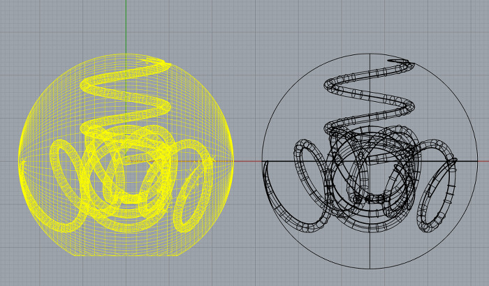
The solid on the right was converted to the mesh on the left. The mesh was trimmed by splitting with a plane, and deleting the bottom chord. The hole in the bottom was then filled to make a closed mesh. This was done to give the object a base, and to reduce the overhang required.


Week Three: Making a Microcontroller

microcontroller_programmer
What an ugly board it is,
wobbly traces, parts askew.
Solid state success.

My process for this week’s assignment was minimal. The circuit board was already taped down. I fixed the origin in x and y. I changed the bit to 1/64″ and carefully tightened it at the z origin. I ran the traces file, and vacuumed up the dust. I changed the bit to 1/32″ and re-zeroed the z axis. I ran the outline file through the fab mod.

The board as milled was a mess. Apparently the surface was not level, and the tape not secure, so the board had some tiny traces of copper still left between the traces. Under a microscope, with a tiny chisel, I cleaned up the board and determined that the traces were sufficiently thick to solder to.

I then grabbed a parts list with double stick tape, and populated the tape with components. Next came soldering, my first attempt at using surface mount parts. The only parts square to the board are those with a fine pitch and multiple pins, which would not make the right connections if off at an angle.

The board was so ugly that I expected it not to work. To my surprise, it programmed up just fine.

As good practice, I will mill up another board, and populate it, with the goal of a pretty pcb that works.

Second attempt at a board

At the Harvard lab, I scraped the sacrificial layer with a ruler to smooth off the burrs on the over-cuts of previous users. On a new piece of pcb, I placed two long pieces of double-sided tape, long axis of board, extending beyond the edges of the board, with no wrinkles or bubbles. I placed the taped board so the long axis corresponded to the y axis of the Modela, with firm pressure to affix the tape.

After checking the printer name, I zeroed the x and y axes, before touching the 1/64″ bit to the surface for the z zero. I ran the fab module on the traces.png file, and milled one board, and then moving the y zero over, another board. I then returned to the origin, changed the bit to 1/32″ and zeroed z, so I could cut the boards free.

The first run of the inside.png file resulted in a cut on the first go around, but no more on the next two. After fruitlessly fiddling with the module, Sarah J. suggested that perhaps I had zeroed z too close to the board, and the cut wasn’t proceeding for mechanical reasons. I raised the cutter head, dropped the bit another 1/2″, and re-ran the file. Problem solved.

Under the dissecting microscope, 7x stereo, a chunky chaff of copper was observed along many of the cuts. I cleaned the boards by hand with a needle, running it gently around the traces where the chaff was. Here is the result:clean_board

When I have a quick minute I will populate the boards with an eye towards heuristics I can share.

Week Two: Laser Cutting a Kit

The assignment was make a kit with 2D elements which connect to make something 3D.

Here is an idea for a fire starter, consisting of a ring of three rectangles connected by tab and slot, with a slitted cut out acting as both louver and fuel.

f_s_test_1

A flame tornado forms when burning fuel drives a chimney which draws in air from the side, through louvers giving the air angular momentum some distance from the center. The spinning air feeds the fire in the center with a high angular velocity.

I decided to forgo the chamfered slot pair connection in favor of a tab and slot, a stronger if less elegant way of holding the elements together in a ring. The tab and slot construction was fast and robust. One prototype was thrown around the shop, and twisted to invert it several times, and still held fast.

f_s_test_2

I made an .svg file in Inkscape.  First, I drew the rectangle with tab and slot. Then an open ended rectangle, with cuts doubling until the fingers at the closed end of the louver are many and small.

fire_starter_o_e_3x6ver5

The final version of the .svg file included color coding of lines to force the sequence of cuts. The software driver for the laser [model] included a “cut outline last” option, which was not sufficient ordering to allow for a clean cut. The option I used was “cut in order of colors,” which in this case was black, red, green, yellow, etc. The line color also held speed and intensity parameters; black, green, and yellow make the same full intensity cut, red at 6% of that to just cut the surface.

I made several iterations of the bifurcation pattern, which would be a good application for a design tool page. The relevant parameters are chimney diameter, bottom chamber height, and louver cut pattern.

Here is the fire starter ready to go, in a rusty charcoal chimney.

f_s_test_3

There are two symmetrical ways to make a ring of tab and slot rectangles, with the tab on the inside as shown, or the tab on the outside, which makes a more circular ring. In this case,  the triangular arrangement makes the ring hold in the chimney, without falling out when turned over.  I underestimated the size of the chimney by an inch.

f_s_test_4 Loading the chimney with a layer of charcoal for test.

f_s_test_5

Just after lighting the center of the fire starter with a barbeque lighter.

f_s_test_6

I shot a quick movie of the fire starter in action.

The charcoal was well lighted by the structured cardboard.  After the fire starter finished burning, I moved the chimney to examine the ashes. The cardboard burns down to a fine white ash, and the charcoal is burning well.

f_s_test_7

Week Two: 2D Cutting and Picking

2D Cutting and Picking

I had a great time with the Roland Camm1 vinyl cutter, using the fab module.

I learned that the vinyl cutter has to be set to accept parameter changes from the fab module, and that the mod_server.js will look at the local file mod_defaults.js, which would allow us to print from Windows without pasting in the printer path each time.

For my laptop sticker, I downloaded a grey scale bitmap image of a letter and line representation of a benzene molecule.

I used the fab mod to trace the bitmap, varying the threshold to change the line thickness, settling on 0.6 for the file.
The following was cut at 200 dpi,  70gf and 2 cm/s, resulting in a 3″ x 3.5″ decal.

Weeding on the adhesive tape lets me me apply the decal with no post processing.

An alcohol wipe of the target surface to remove finger grease,  then wait a minute for evaporation. Apply and burnish. Pull the backing off at a sharp angle. The blue tape releases well and is very flexible, more so than the [other sticky backing material].

A small graphic of a benzene molecule, cut on the vinyl cutter, is trimmed before fixing it to blue masking tape.

benzene_3

benzene_2

Vinyl side down on the low tack blue masking tape, adhesive side up.

benzene_4

Starting to pull the vinyl away from the tape, slowly and carefully.

benzene_5

As each section around the edge came up, I cut away the excess with scissors, to keep the waste from grabbing adhesive to adhesive. A previous attempt failed in seconds, when the near 180° pull shear angle dipped and adhesive grabbed. Woops, good thing I made three of these.

benzene_6

Getting there. Folding the blue tape onto itself made the tape backing easier to hold down, when applying counter force to the peeling.

benzene_7

The tiny rectangles of the partial bond need to be carefully managed to keep them in place on the blue tape. So close…

benzene_8

The finished product, which application to my laptop cover, burnishing and peeling, went smoothly with a complete transfer.

benzene_1

Week One: Final Project Proposal

I am in the course, this MAS863.14, and the first assignment is to make a final project proposal. An iteration of that proposal is now a wordpress page, viewable above. The original idea came from a conversation with Gus Rancatore, who was apologizing for over-cold ice cream. Why so cold?  Transported with dry ice.

Ice cream can take further cooling from its ideal eating temperature while remaining ice cream upon return thereto. The same is not true for temperature excursions above freezer temperature. Melting is catastrophic; even getting close will cause crystal coarsening, degrading the quality of the ice cream.

Too little dry ice is way worse than too much. So the standard operating procedure is to throw in enough to keep the ice cream in deep freeze.  In a box with good insulation, the dry ice will slowly sublime, making a temperature gradient from -78.5°C next to the dry ice, to room temperature at the surface of the box. This argues against having ice cream in contact with the dry ice.

Dry ice is a great source of cold carbon dioxide gas, at ~ -80°C. A box of dry ice with a fan blowing the cold gas in a loop over stacked ice cream containers, cycling on and off as needed to keep a temperature sensor at the ideal serving temperature of -8°C.

I propose to make a portable, solar powered, dry ice cooled, thermostatic, ice cream freezer.
My computer was in limbo for a couple of weeks, so I drew up a first draft in a note book.

freezer_sketch

So now I am looking at what modeling software to use. I didn’t take one of the SolidWorks licenses. My goal for the class is to use all free software, but there is some other Antimony out there in the aether which is not the correct Antimony, which just crashed.

I ended up using Rhino as a free beta on the Mac, and it served it’s purpose. SolidWorks is still on the agenda. Antimony was great for making my spherical potential wells; it too is due further use.