So the thermistor bridge boards from last week will now take a program. So far the values read change on temperature change, but no T in °C yet.
Charles Fracchia suggested a quick detour over into ArduinoIDE and CoolTermMac for communication. Rapid spotty success. Loading Software.Serial takes up 90% of the program memory, yikes.
Lots of use of delays. I guess I should get used to using the microsecond delays, because most of the warnings about settling times are on the order of microseconds. Also turning everything else off. Seems like just setting a bit or two, maybe another control register, let me see…
That was fun.
This week’s project ate last week’s. More to the point, I didn’t hit archive software before major editing, thinking to “save as…” hitting “save” and finding no undo.
Oh my.
I had just gotten to the point where reading the differential channels one way vs. the other gave the same magnitude. The RTD bridge was responsive with 20x gain, while the NTC bridge moves nicely at unity, about the same excursions, 50 units from room temperature to finger temperature, 100 units from room temp. to ice pack. Even without T this will work at ice cream temperatures.
Still not sure about extracting T. Reading about the subject on http://www.omega.com/temperature/z/thertd.html suggests that with four point calibration, 1% accuracy is within reach! Want better? The R/T curve is modeled by a 20th order polynomial. Whee!
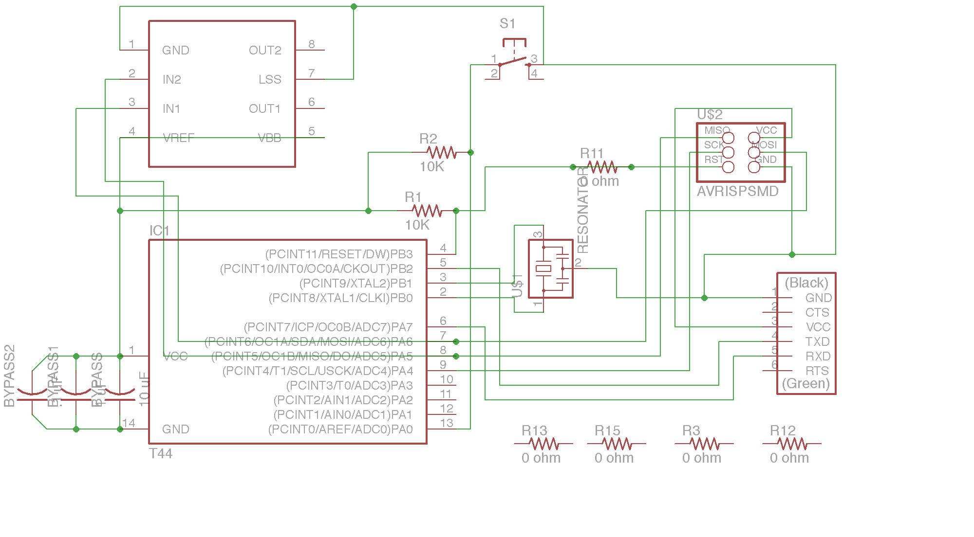 In order to move on to this week’s assignment, I opened up Eagle and got to work. I modified the kTbug schematic after saving it as a new project.
Eagle has a nice way of keeping details in order. The switch is new, and to keep it simple, I put in an external pull-up resistor. Three bypass caps, 10uF, 1uF, and 0.1uF are on the logic side power, and the A4953 H-Bridge calls for 100uF electrolytic and 0.22uF ceramic caps for decoupling the Vbb power. The 9V battery seems to be okay without those, perhaps at this low power, in an application where distortion is a feature.
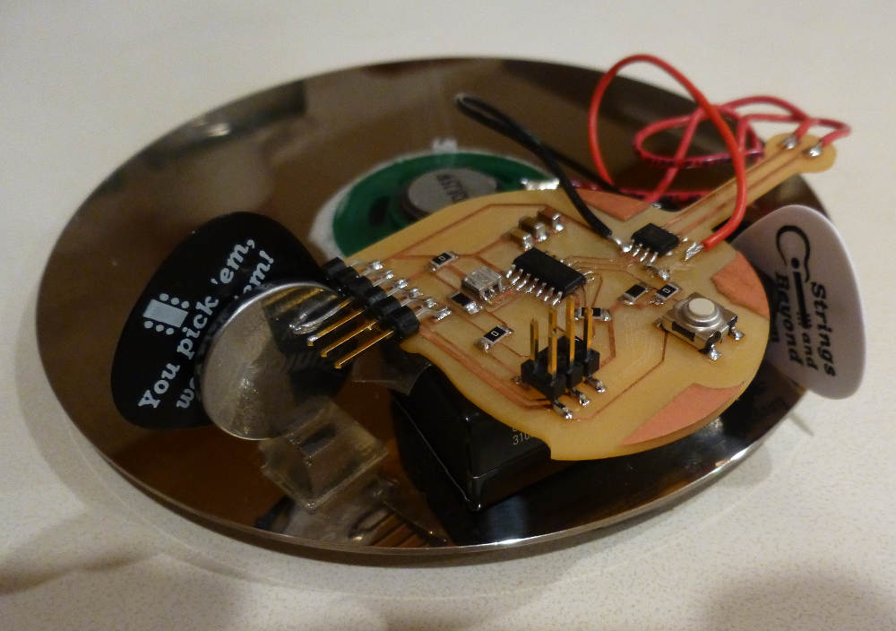
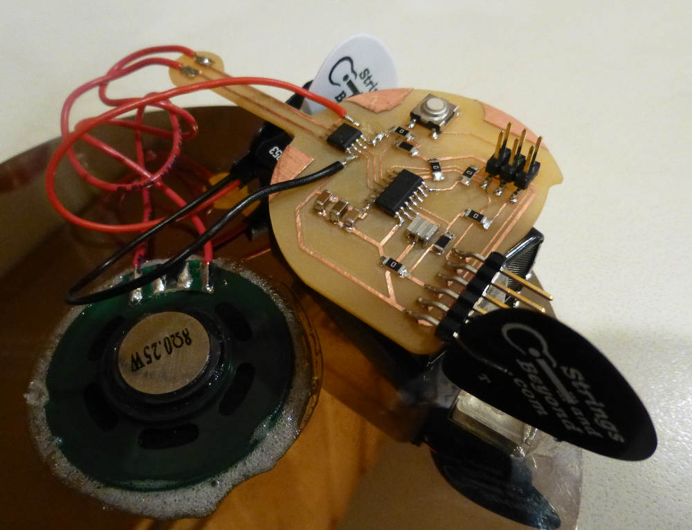
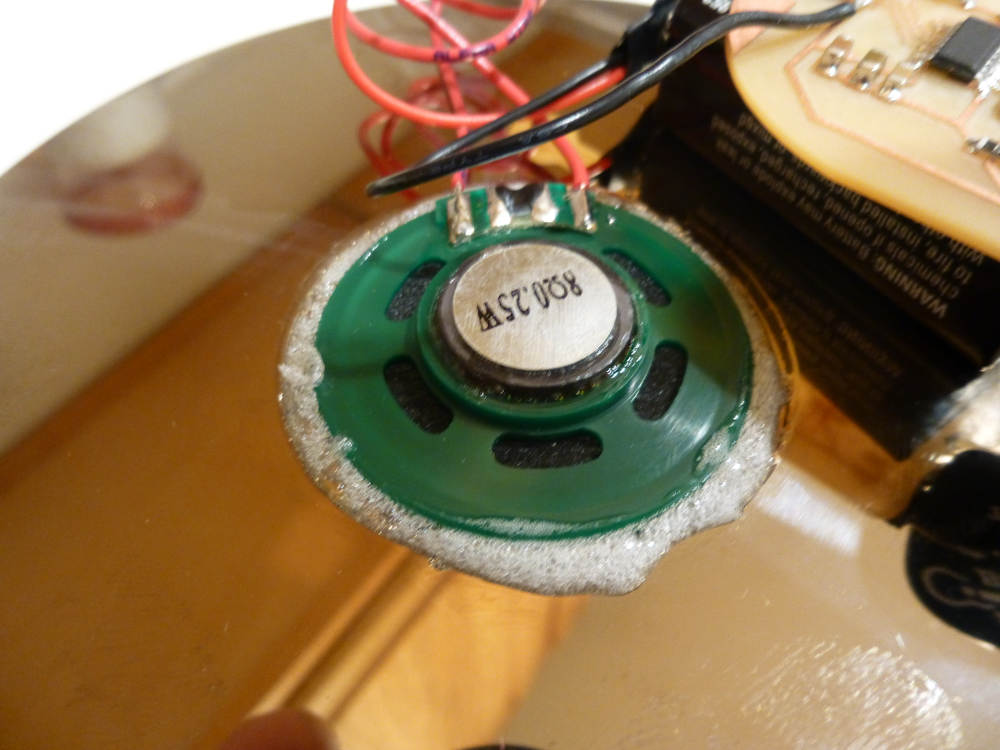
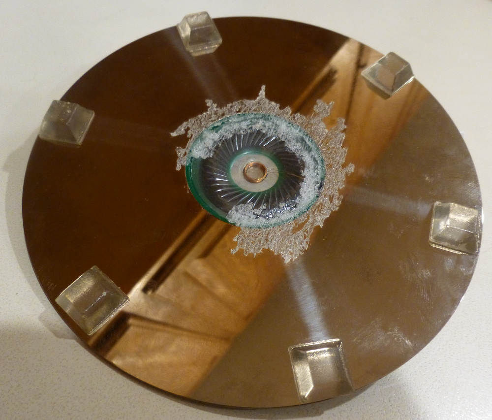
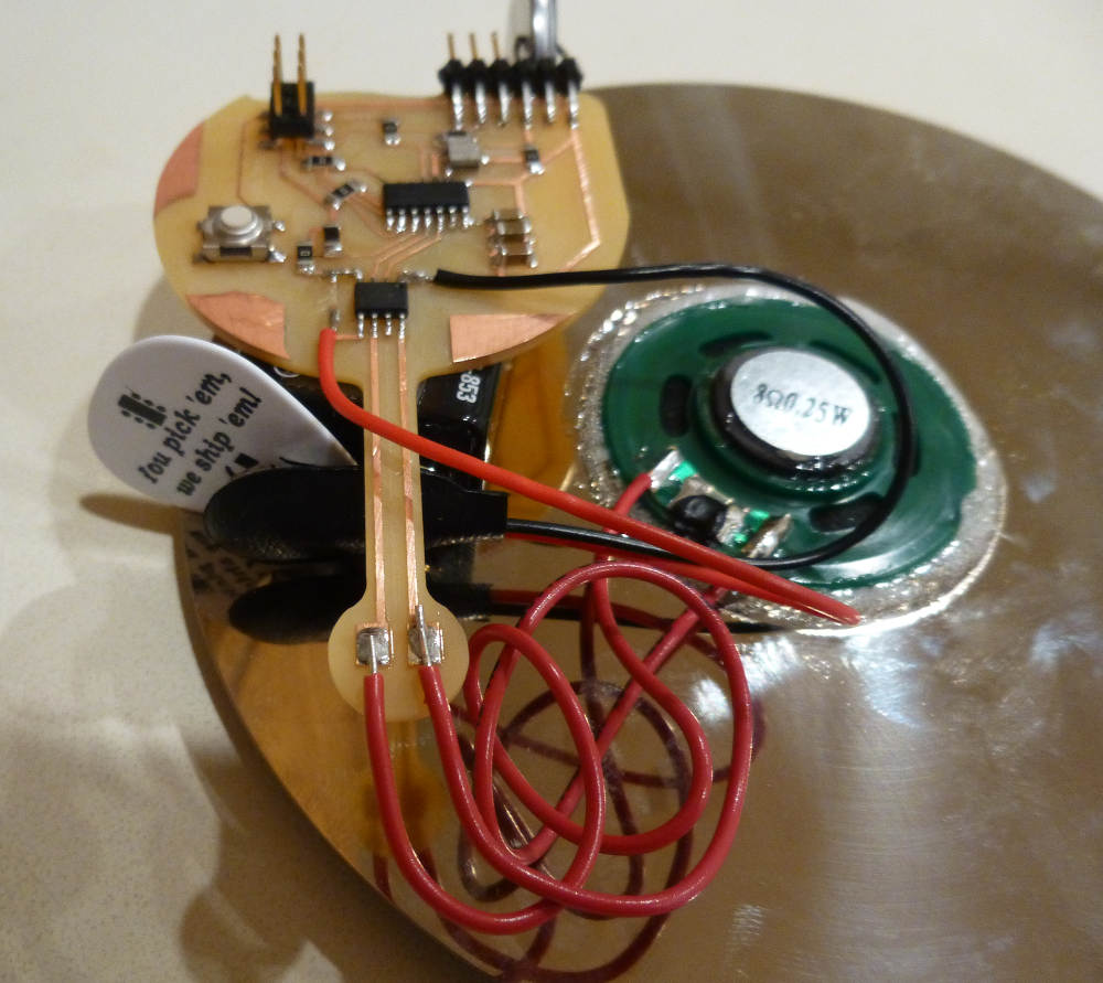
The board is cut, and populated, with the same geometry using the neck to put solder pads at the end. This allowed use of the 1/2″ speaker with spring connectors as a quick test. Here it is shown connected to a 0.25W 8Ω speaker, which is glued (Gorilla) into the hole of a 5 1/4″ HD platter, as a baffle. Small plastic feet hold the platter off the surface, making a resonant volume. Improves coupling of speaker to air, makes louder. Does it boost the high frequencies?
The software is written in ArduinoIDE. It tests for a button push; if the button is pressed, it makes a “pew” sound by PWM in software. If the button is held, six “pews” sound, with an increasing delay between. After six “pews”, if the button is held for three seconds more, five seconds of random noise indicates that the coils have fried.
Things I have learned: The H-Bridge A4953 is boss, but will not work with only Vcc, needs a Vbb, in this case a 9V battery, on a battery clip with leads soldered to Vbb and GND. Then it works hard enough with a 50% duty-cycle to make the speaker coil very hot. PWM tests at low duty cycle first!
I forgot a power switch or two again. The FTDI header makes a nice impromptu battery holder, with a thin guitar pick as a switch. Must learn how to power down the ATt44, or add slide switches anyway.
Some more images:
A video of the first pews: