When my first board did not respond to the ISP, uninitializable, I figured it was a solder problem. I inspected it under the 7X stereo dissecting microscope, no problems in sight. Good looking 1206 components, those thermally sensitive resistors.
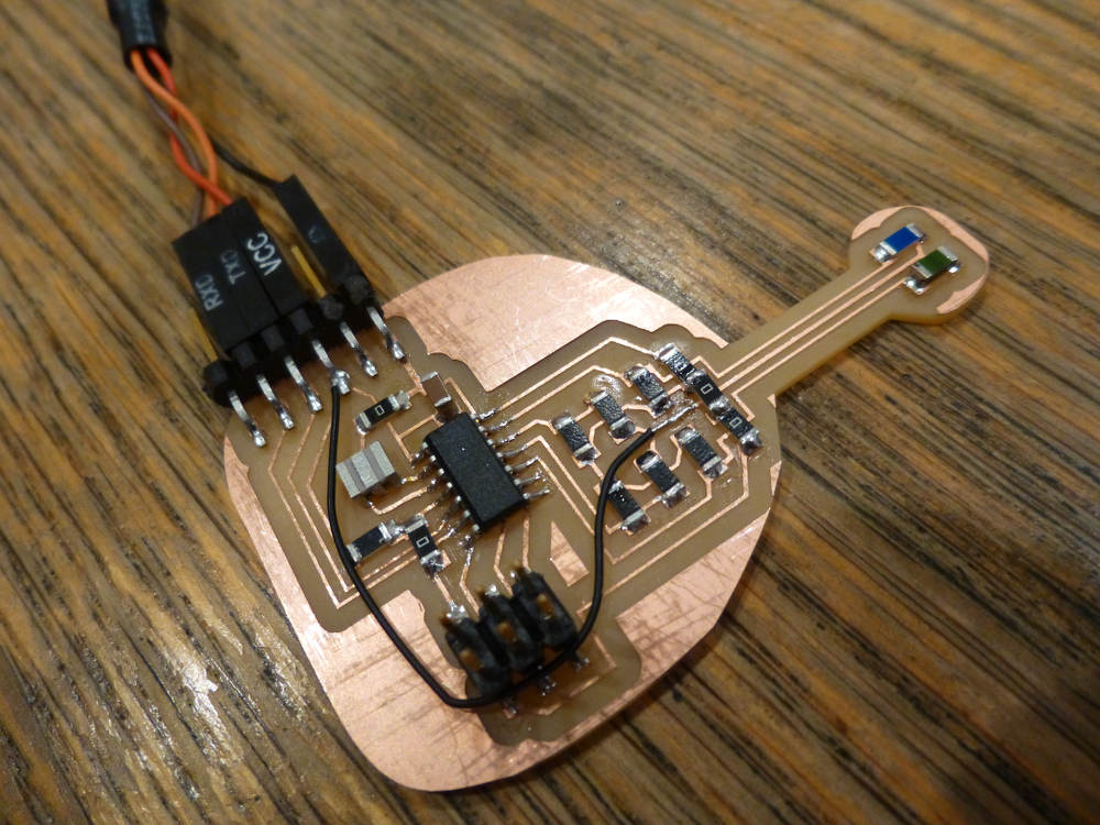
The board extends the thermistor legs of two bridges out away from the rest of the circuit, the head of the bug. An RTD, blue, on the left, and an NTC, green, on the right.
The thorax consists of jumpers and the rest of the resistor bridge, and the abdomen is the ATtiny44A, running at 20MHz with a ceramic resonator.
Why doesn’t the ISP see the board?
Back to Eagle lite software, where by dint of repetition, I began to see the logic of the process, route, rip, repeat. The drawing primitives provided a way to curve the outline layer of the board, and extend the neck of the bug to the limit of the small circuit boards. Group selection and moving involves holding a command key and right clicking, which is non-intuitive and took a while to master. Lucky, I had that time.
 I cut a new board. Populated and soldered, super careful.
Didn’t initialize. ISP says Yikes! Actually, AVRDUDE said Yikes, when the return code of the AT44 was #0000000000000000.
Did I overheat the processor? Am I that heavy handed with the soldering iron?
So my process lead me back to Eagle, where I re-routed every line I could to make it a bit more robust. I cut the board, and examined it. I still was not seeing the missing connection.
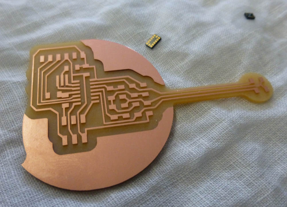
(Above the board is one of the tiny accelerometers, cyanoacrylate glued to a piece of linen, waiting for some 28 ga. wires and solder, perhaps to make a flexible breakout for the part, allowing it to be attached to, say, a violin back under test. It was good practice; I managed to attach five leads.)
A thorough examination of my board, next to a working board, showed me my missing clock connection. I used the fine lead wire to jump the ISP header to the clock pin. And it works.
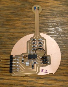
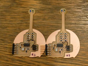 Two boards to compare. Board #3 has thicker leads and wider offsets on the milling.
The most important piece of advice for the Modela: be careful to only have one layer of tape, say two pieces on the long axis of the 2″x3″ board, which extends beyond the edge of the board. Any folds in the tape, or double layers, will throw off the level. Even the raggedy bit of tape at the cut end can be a different thickness, which is why the tape should extend beyond the edges of the board.
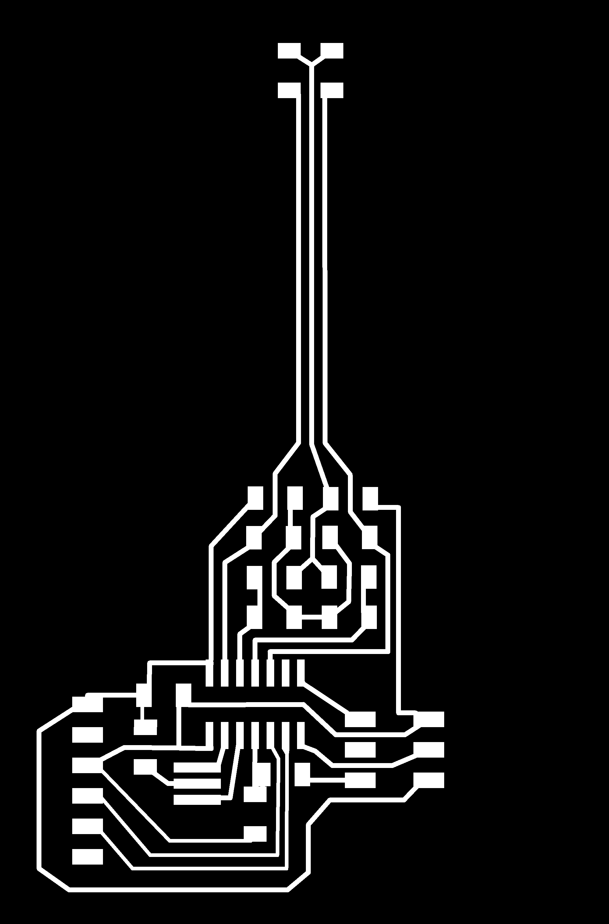
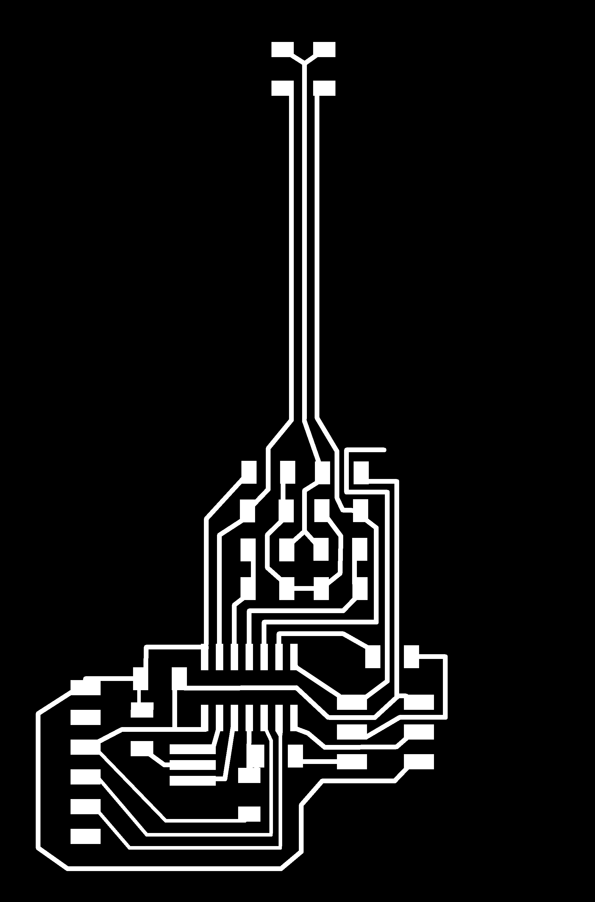
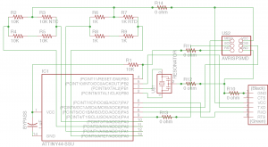
Here is the circuit board trace file. On the left, as cut, with missing lead. On the right, the clock pin is connected to the ISP header with a zero Ohm resistor. For later use, the MISO and MOSI connections are extended out to be available to the right side of the board.
Other lesson of the week: a close examination of the schematic would have saved me some time, but as that time was spent jamming away on Eagle, I count it well spent. I honed the design of the layout several times, learned how to add zero Ohm resistors as jumpers, and tweaked the trace to pad connections for easy cutting.
Other time spent cutting and soldering was equally valuable as practice. Now I have three thermometers.
As for the communication and reading out the temperature, no success with Python talking to the board by FTDI. The code for reading both differential bridge inputs, and comparing the two sets of data, is still in the conceptual stage.
Finally, the extended leads will probably need shielding. My next board will have two copper layers, with the bottom as a ground plane. The whole board will be encapsulated in clear epoxy for use as a voting thermostat input.