What an ugly board it is,
wobbly traces, parts askew.
Solid state success.
My process for this week’s assignment was minimal. The circuit board was already taped down. I fixed the origin in x and y. I changed the bit to 1/64″ and carefully tightened it at the z origin. I ran the traces file, and vacuumed up the dust. I changed the bit to 1/32″ and re-zeroed the z axis. I ran the outline file through the fab mod.
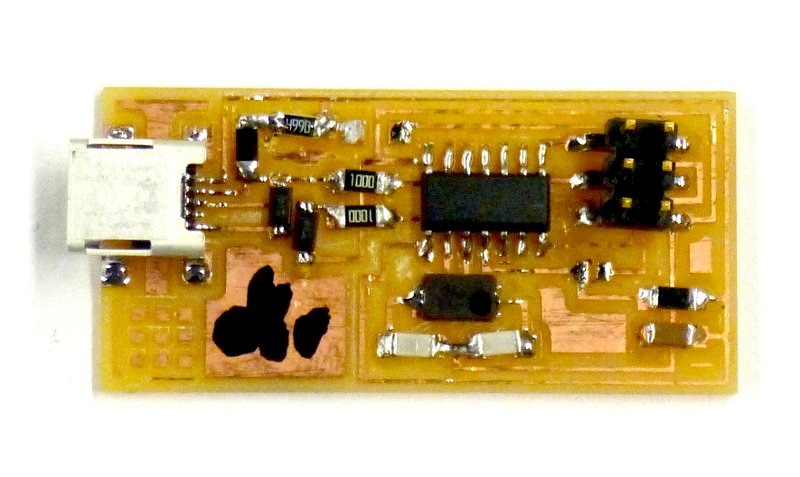
The board as milled was a mess. Apparently the surface was not level, and the tape not secure, so the board had some tiny traces of copper still left between the traces. Under a microscope, with a tiny chisel, I cleaned up the board and determined that the traces were sufficiently thick to solder to.
I then grabbed a parts list with double stick tape, and populated the tape with components. Next came soldering, my first attempt at using surface mount parts. The only parts square to the board are those with a fine pitch and multiple pins, which would not make the right connections if off at an angle.
The board was so ugly that I expected it not to work. To my surprise, it programmed up just fine.
As good practice, I will mill up another board, and populate it, with the goal of a pretty pcb that works.
Second attempt at a board
At the Harvard lab, I scraped the sacrificial layer with a ruler to smooth off the burrs on the over-cuts of previous users. On a new piece of pcb, I placed two long pieces of double-sided tape, long axis of board, extending beyond the edges of the board, with no wrinkles or bubbles. I placed the taped board so the long axis corresponded to the y axis of the Modela, with firm pressure to affix the tape.
After checking the printer name, I zeroed the x and y axes, before touching the 1/64″ bit to the surface for the z zero. I ran the fab module on the traces.png file, and milled one board, and then moving the y zero over, another board. I then returned to the origin, changed the bit to 1/32″ and zeroed z, so I could cut the boards free.
The first run of the inside.png file resulted in a cut on the first go around, but no more on the next two. After fruitlessly fiddling with the module, Sarah J. suggested that perhaps I had zeroed z too close to the board, and the cut wasn’t proceeding for mechanical reasons. I raised the cutter head, dropped the bit another 1/2″, and re-ran the file. Problem solved.
Under the dissecting microscope, 7x stereo, a chunky chaff of copper was observed along many of the cuts. I cleaned the boards by hand with a needle, running it gently around the traces where the chaff was. Here is the result: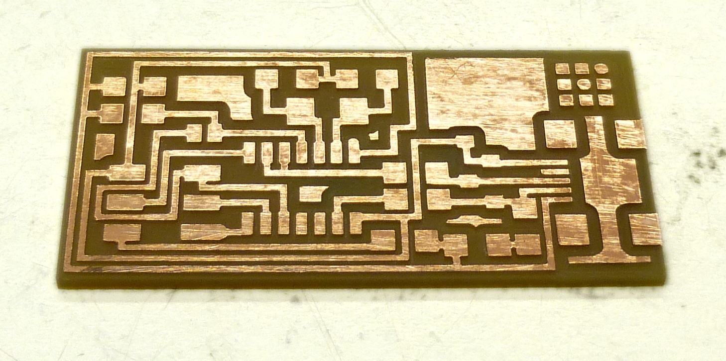
When I have a quick minute I will populate the boards with an eye towards heuristics I can share.