This weeks project involved designing a board with an output device.
I decided to make two boards, one with an h-bridge that would control a dc motor,
and one with an led array.
H-Bridge Board
Board Design
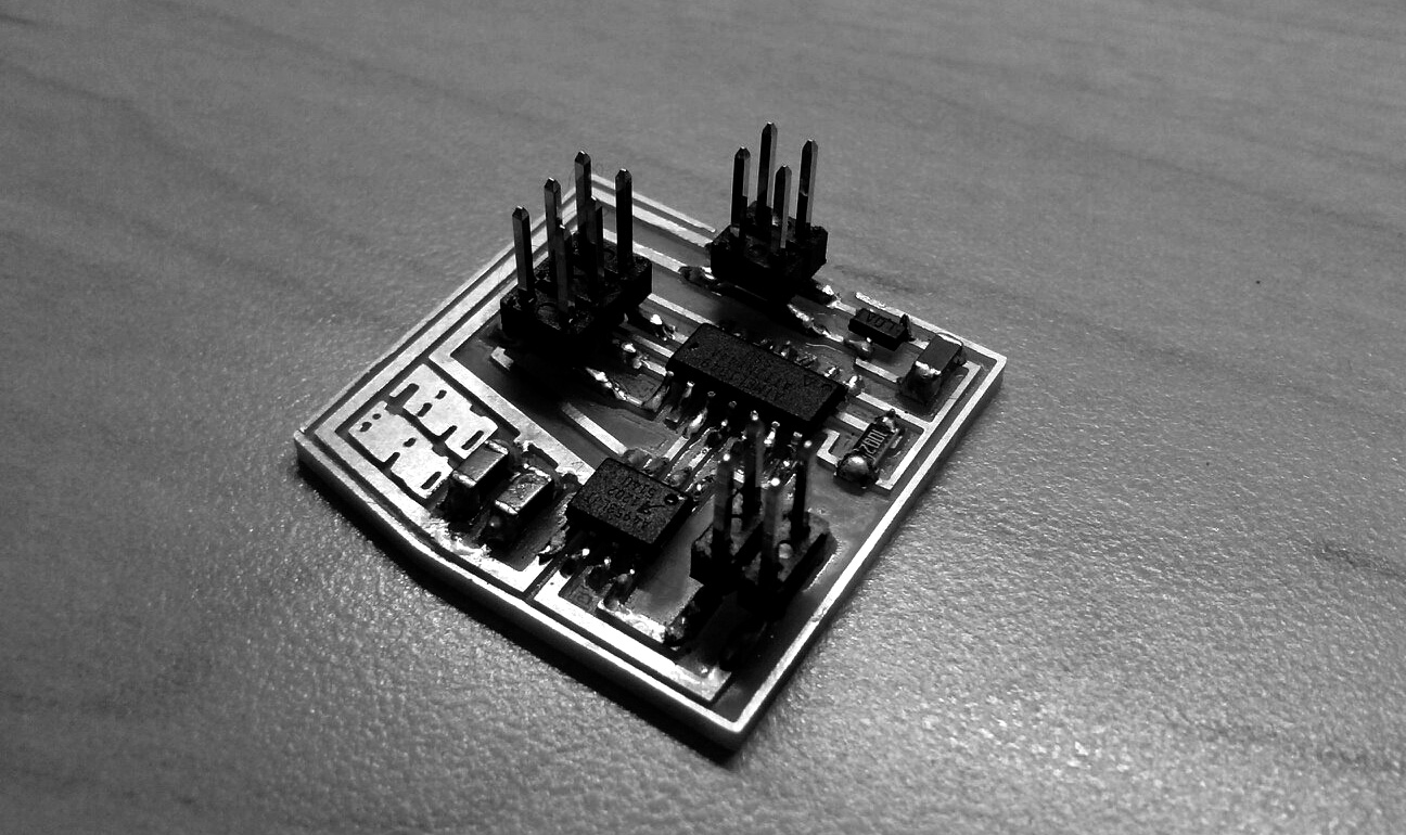
I didn't make many changes to the original designs of both of the boards to save
time and be able to build both of them. This board uses an external input of 9V to
drive a dc motor. The h-bridge allows me to control the on and off state as well as
the direction of the rotation.
Programming Board
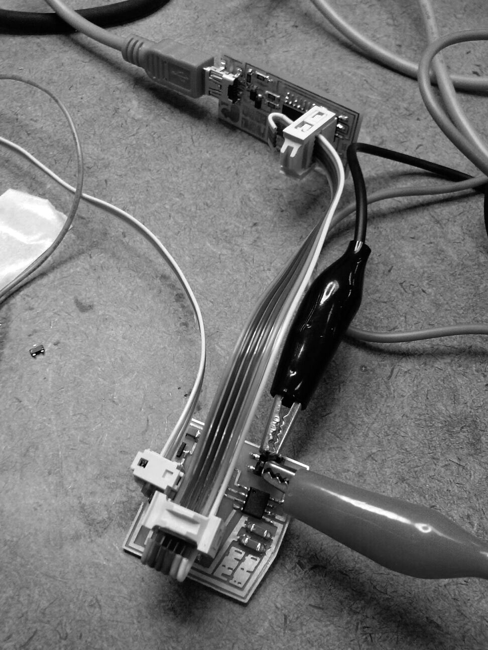
I programed the board using the fabISP through the Arduino IDE.
Final Configuration
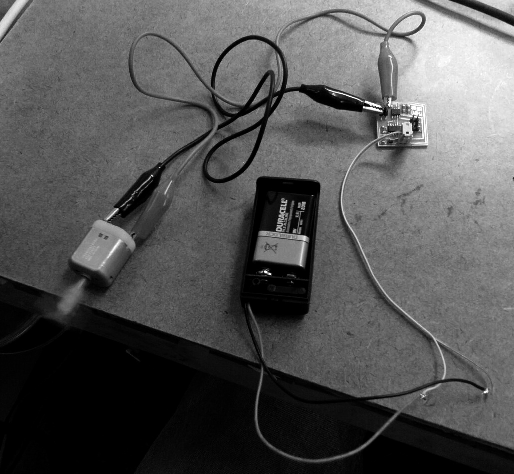
The motor was working just with the external battery. It was programed to spin on
one direction and to switch directions after a few seconds.
LED Array Board
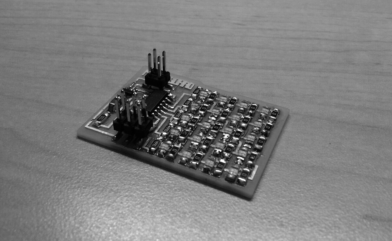
The second board I wanted to test, was an LED Array board. I controlled the LEDs
through Charlieplexing. I also programed this board using the Arduino IDE.
First, I needed to understand the principles of Charlieplexing. This was a helpful
website. http://www.maximintegrated.com/en/app-notes/index.mvp/id/1880
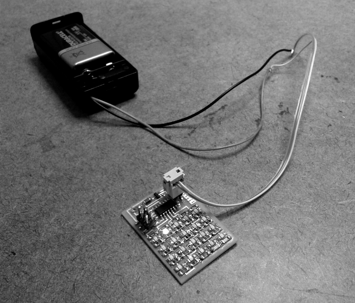
Final Configuration
Programing the board in Arduino was also a challenge. I used different pinModes
(OUTPUT,HIGH - OUTPUT,LOW - INPUT) to define three different states of the pins
(VOLTAGE OUTPUT - GROUND - IDLE STATE).
Then I tried to understand how combining different pins turn on and off the LEDs.
I made the following chart where each LED in a row and column corresponds to a certain
pair of pins.
____1___2___3___4_
1| 2,1 3,1 4,1 5,1
2| 1,2 3,2 4,2 5,2
3| 1,3 2,3 4,3 5,3
4| 1,4 2,4 3,4 5,4
5| 1,5 2,5 3,5 4,5
I created a method that would turn on an LED through the translation of its
coordinates to the combination of the pins.
void ledHIGH(int x,int y){
if (x<y&&y>1){
pinMode(x,OUTPUT);
pinMode(y,OUTPUT);
digitalWrite(x,HIGH);
digitalWrite(y,LOW);}
else {
pinMode(x+1,OUTPUT);
pinMode(y,OUTPUT);
digitalWrite(x+1,HIGH);
digitalWrite(y,LOW);}
Finally I iterated through the grid.
Final Result