Methodology
Ridiculous Challenges and Setbacks Faced: I think this is an important paragraph to have, because it was a vital part of the machining process. I think it’s most definitely noteworthy to be able to identify key problems and see in exactly what way they delayed my process, and then be able to figure out how to have avoided them or how to work around the issues. It’s an important thing to be able to do I think, troubleshooting and acknowledging imperfections in a process, especially one that is human labor intensive. I learned about budgeting more time than anticipated to complete a job, and to expect to have to do multiple run throughs when things don’t go as expected.
There were some restrictions that came from working on this project post term. First off is that some of the supplies we had from certain weeks were no longer available, so in particular I scraped the idea of doing a composite. Additionally, I did have to beg off a bit of shop time from a few sources around campus that also had limited hours, so working that around a class schedule and not being able to machine at 3 am….little bit limiting, but maybe also healthier for my sleep schedule? Then came the snow days and vacations where show owners were traveling….so shops were closed and I was just cooped up wishing that I had a shop in the basement of Senior Haus (if only MIT were so kind). Parts that I had ordered came in late, and then ultimately some parts were even defective. My last major restrictions came at the best time of course--physical restrictions right when it was time to construct my parts. Wrestling I have learned is a dangerous sport. My first problem was from a concussion I sustained mid January or so…..that put me away from loud sounds/bright noises for almost 3 weeks until I had recovered. The next and still present issue is broken bones in my dominant hand, which I sustained during a match. I’ve learned that I’m not as ambidextrous as I thought that I was, and soldering surface mount components with a wrapped up hand or the off hand is hard. Apparently I lack spatial awareness, and in addition to my splinted up mess of an arm I also managed to burn myself nicely at all of 720 degrees with the iron.
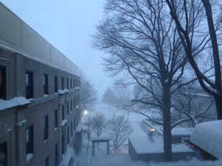
Set back of a winter wonderland in Boston. Yay official state of emergency.
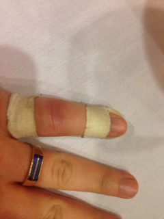
Another setback....most unwrapped picture that I have of my nasty broken finger.
Electronics
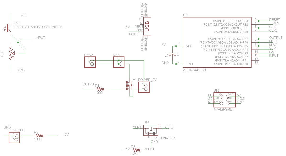
Modela Mill: the modela is the first method I attempted to use to cut out my boards. I’m actually very comfortable with electronics production and I did well during that week of class. I’m not at all a bad hand at soldering and the modela is a lot of fun, something I would want to definitely own if I had my pick of little machines. Anyway, that being said, I ran into some unexpected problems. One day the modela just flat out fritzed out on me, and I was having issues running the module. I just threw my hands up, came in the next day, and problems were magically solved. I taped up a PCB board (one of the last big clean ones because the IDC was running low on supplies) and slapped it on the mill, zeroed out and was ready to go. Less than a minute into the operation, there was an ugly scratch dragged across, a nasty snap sound and I paused the job. Took a nice good look at the bit…..and it’s broken. I went to Charles somewhat shamefully to let him know that I had busted the only 1/64 endmill that he had in the shop. He to my surprise produced one from his desk and I went back into the shop. I changed some cut depth settings and also adjusted the z height before starting the job again, and I changed out the board of course. Going back in for round two….it’s cutting strangely deep in some places before the same issue happens once more, ugly scrape, snape and this time the real last 1/64 in the shop was gone. I had Charles inspect everything I had done because I was frustrated and honestly couldn’t figure out where I had gone wrong. Charles looked over my work for several minutes and was similarly stumped, until he saw me pull the most recent board. Holding it up for examination, he determined that the board had warped most likely in the weather, such that the center was raised up. With this problem the modela would find zero at a reasonable location, but thinking it’s dragging above the plane to it’s central location it would have no clue that other areas of the board were not flat, and that’s where I literally ran into problems. So completely out of luck now on the modela with the broken endmills and not a single board that Charles thought was salvageable due to all the warping, I moved on and started looking for alternative methods to make this board.
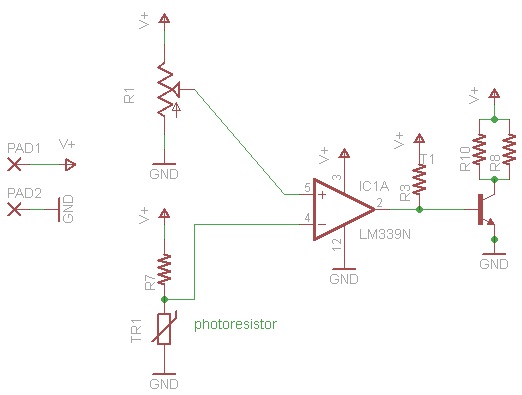
Breadboard: I used a breadboard briefly in order to test out my new circuit. They’re handy in that they’re able to quickly test whether or not a circuit is in the correct configuration to perform what you’re asking of it. It’s not a permanent solution by any means, rather a quick prototyping method. I checked my second board schematic with this. The only downside is that it isn’t something for surface mount components, so I wasn’t able to lay out my original design and see if it was going to function well barring the manufacturing process issues.
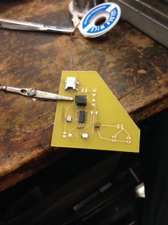
Acid Etching: Acid etching is a new method that I was forced to learn after the failed attempts with the modela mill. It ultimately seemed like it was the best course of action to provide a board in a timely manner. The way it works is that you take a circuit design (in my case something I’d sketched up on Eagle), and onto glossy photo paper you print a mirror image of the resist. You put the paper onto the board, with toner applied, and shove it into a laminator which uses heat to melt the image onto the board. Once that step is complete, if your image is clear, then you can put it in the acid bath. It has to go about 30-40 minutes, where it’s agitated at room temperature in ferric chloride, which strips away all the copper not covered by the negative of the circuit layout. One lesson learned is to make sure that it’s mirrored properly, otherwise you won’t be able to solder the parts in the correct configuration….i.e., sad board is sad.
Physical Structure
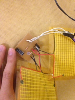
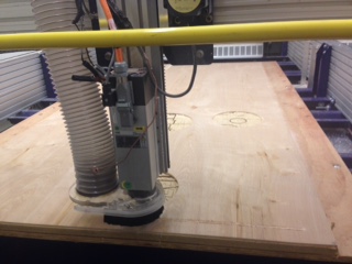
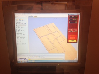
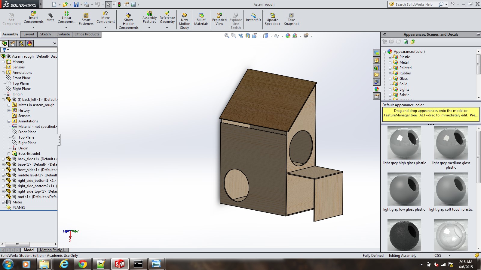
Shopbot (yay CNC!): So the shopbot was the primary tool that I used for the physical structure. I took my Solidworks assembly, turned it into a couple of drawings and arranged them such that they would be able to be cut out of a large 4x8 piece of wood that I purchased from Home Depot. I then exported that file as a dxf and loaded it up onto the shopbot software. The settings I used were the pocket cut with the outside trace to avoid sizing problems due to the kerf of the bit. Took two jobs to cut all of my pieces due to the size and layout.
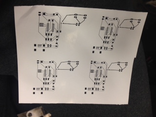
picture of the printed board negative that's going to be put on. Honestly this kind of reminds me a bit of casting week.
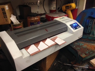
acid etching here's the part where the image gets melted to the board before the agitated bath.
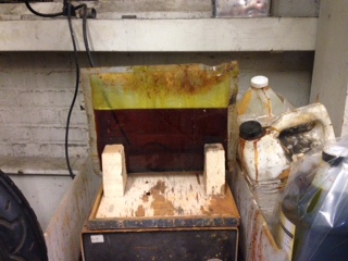
Here's the actual agitated bath process