ss="row">

4.140/MAS.863

Where Emilee Johnson Tries to Make Almost Anything

Output Devices

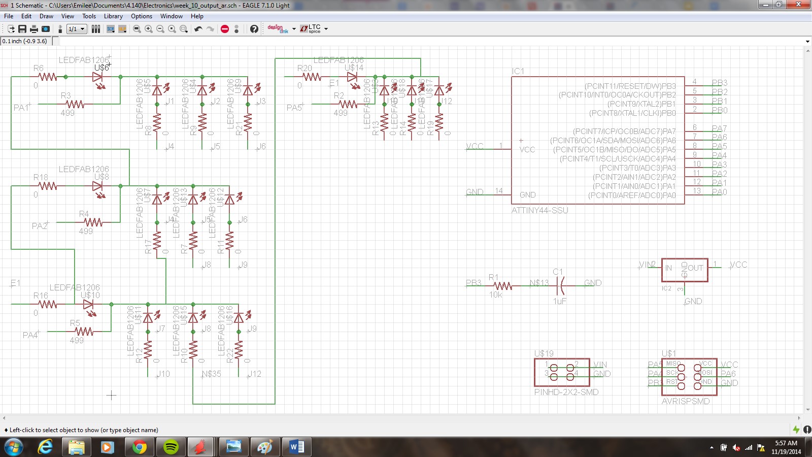
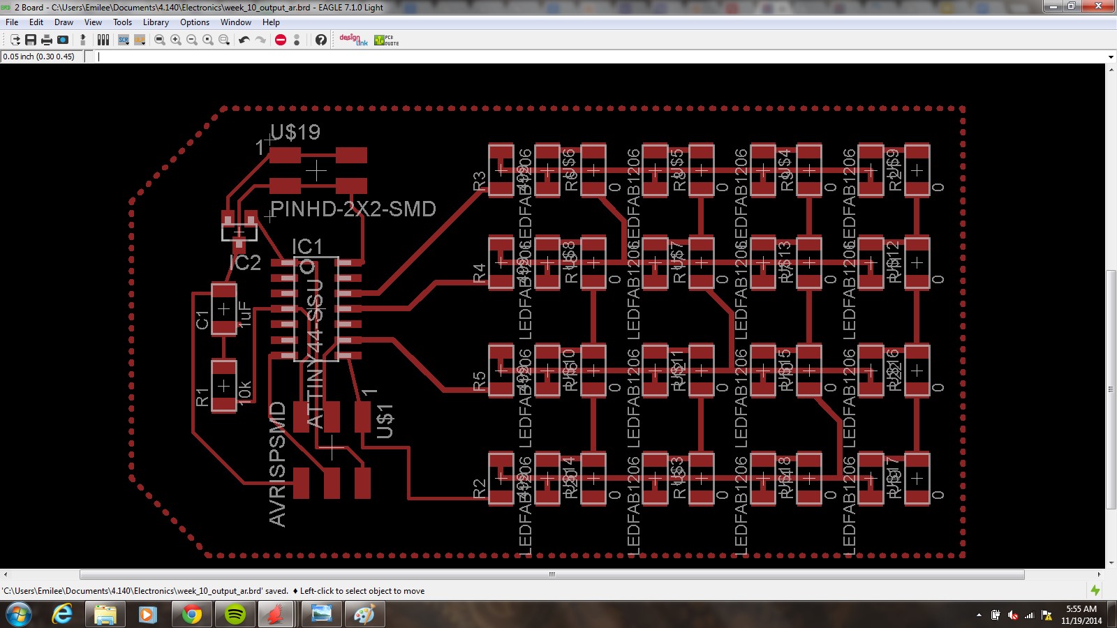
So....output devices. This week we had to design our own board and make it do something. I didn't venture particularly far out this week in terms of creativity, but it was a very valuable week for me because I have decided to update my final project, which I will talk about again shortly. Anyway, so I chose to modify Neil's board and simply reduce the number of LEDs to make a square setup. My objective was to play with Eagle a bit and also create something that I can try out different codes over the next week or so that directly relates to my plan for my final project.

Final project update! I will include some sketches as soon as I have them and start posting the final project link over the next week with information about my BOM and manufacturing process. I decided to scratch the chess board idea finally for a few reasons. One of the bigger ones is that someone's already done exactly what I wanted to do not too long ago in this class (which I did not realize at the time) and I also felt like it was a bit out of my depth and too specific to some programming specifics that I didn't particularly care for. Now what I'm interested in doing is creating a speaker set up for my room. I'm going to build two speakers of hopefully reasonable quality, which will be mostly an assembly project. The fun addition that I want to add to this set up is a (large) audio spectrum analyzer that I can mount on my wall over my external monitor and where I plan to place my speakers. This is why I was interested in trying out the LEDs this week. I think it's going to be a tedious and involved process on the manufacturing end to build the set up (because really there's no fun in just buying the display right?) but I'm actually genuinely a lot more excited for this idea than my first one and I think it's something that I would get a lot of functional use out of, as well as something that I've never even considered trying prior to taking this class.

Project 10a
Well starting from the top, here's an image of the schematic I generated. This week was definitely a little bit tricky. I was really cautious when doing the LED wiring to make sure that I connected everything at the right point. Google images of multiplexing LEDs were definitely a helpful tool just as a sanity check.
Project 10b
I think that my schematic was reasonably clean given what I've been foolish enough to do with the wires in previous weeks and some other schematics I've seen, but it still looked a bit more complicated (in my opinion) than it needed to be. If you thought that was bad though, check out the board diagram. Prior to routing this thing was an absolute mess. I think I spent more time making sure I had things flipped in the right direction and drawing the routes than anything else for this entire project. On the upside, I found some awesome tools in Eagle to make my life easier. So I had a previous aversion to autoroute because I was convinced it was a liar that wanted to make something I wasn't interested in. That's still kind of true, but you can give it a lot more direction than I had previously understood. I changed settings so that it would not consider through holes and wiring the bottom side as an option first off. The next thing I discovered is that I can select a specific route to autoroute and not make it do the entire thing and mess up my routes because it suggested some stupid yellow lines. This was really useful because when I was trying to wire up though the Attiny44 even when I made the wire width a lot smaller, I still was having issues because my mouse was moving too large of gaps to meet clearance requirements. Apparently autoroute is under no such restrictions, and placed things exactly how I was trying to on my own. So I'm slightly more sold on Eagle now although I'm interested in giving Altium a try if I somehow manage to get my hands on it for free.
Project 10c
Modela mill doing it's thing, first run through on my second attempt. I used the 1/64" for the traces, as has kind of become standard for me since we made the FABISP boards way back in the beginning of the semester. This picture is of the first run through...it didn't cut all the way through on the outer boundary so I just made a few adjustments to the cut depth and checked the surface and z axis zero before running it again. I had similar issues with the FABISP and it's not really a big deal. The first attempt I made at milling, it was unable to successfully accomplish the traces, so I had to edit them in Eagle to give more clearance for the endmill. The second go of it was definitely cleaner although for some reason the paths weren't as linear as I would have liked. It's possible that I didn't secure it very well to the plate, or I did something wrong setting up the Modela, but it seemed as to be rounding off some corners and making oddly asymmetric cuts in some areas. Fortunately it didn't affect my second time around overall product.
Project 10d
Stuffed board! My soldering skills are definitely coming along although I wasn't too bad to begin with when I came into class this semester. I feel like this is the first week I started to get Eagle and was able to manipulate things to do what I want instead of being a slave to the software, so I'm a bit less grumpy about electronics this week for sure. Since the board was almost as big as the PCB I cut it into, I decided to just not bother cutting the outline to save some time. The modela was also acting up and messing up PCB boards because for some reason the tape wasn't sticking, so I wanted to get it off the machine with good traces in tact and not risk it. For programming I did not choose to get creative with it this week. I just ran Neil's program from the LED Array section. Over the next week and a half or so I plan to mess around with FFTs and methods that I can incorporate into my audio spectrum analyzer.