Final Project - Nuton - The Electric Longboard
How to Build a Smartphone-controlled Electric Longboard from Scratch!For my final project I wanted to do something that really tests the limits of what we learned - combining CAD, fabrication, (power) electronics, embedded and general programming. More importantly, I wanted something fast, that could carry a person.
That's how Nuton: the electric longboard was born. Nuton is a variation of my dog's name (Newton). It also happens that Newton is the father of classic mechanics, so the name seemed like a good fit.
TL;DR - See this demo video -
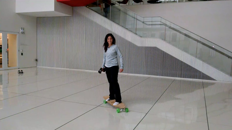
Then, on final project presentation day - Neil Gershenfeld - my professor took the board for a spin!
Now for the specifics.
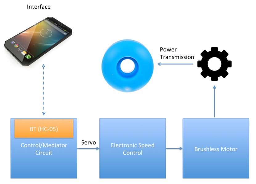
Every good engineering project starts with a block diagram. So here's mine. The plan was to to connect a brushless motor to a single-wheel using two gears and a timing belt. The motor is controlled via an ESC, which is in turn controlled by a custom circuit I'll design and program that has bluetooth support, and that will control the ESC using PWM signal.
The Circuit + Bluetooth module would allow interfacing with the longboard through an app, so that any phone can be used as a remote control.
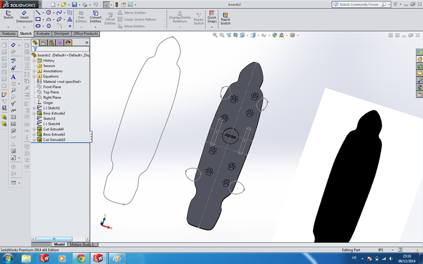
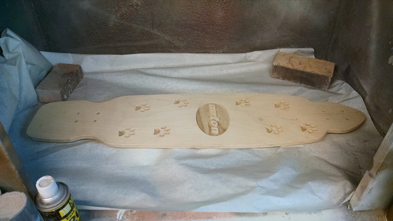
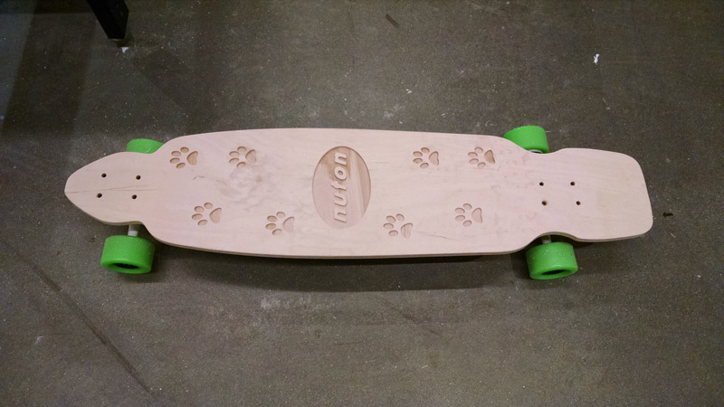
The first step in the process was to design the board. I designed the model in SolidWorks, giving it the appropriate size-contraints similar to existing longboard (albeit somewhat longer, as I really wanted it to be relatively big!).
I used 5/8" Baltic Birch Plywood as the deck's material. It's important to note that a quality BB plywood is required - do not get the generic home-depot stuff that's actually filled with some filler material, and is not constructed of many layers of plywood.
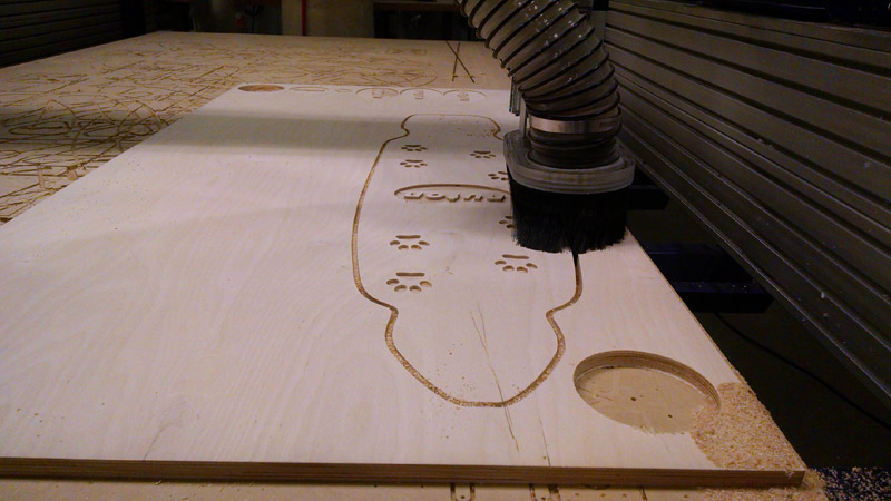
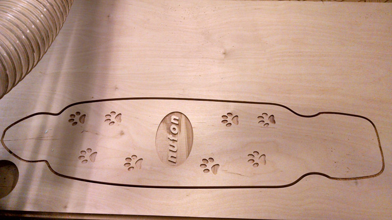
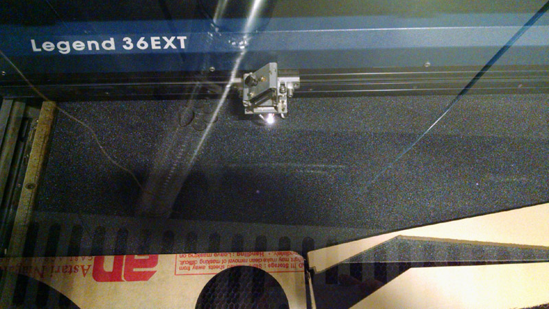
The original SolidWorks model failed to give nice results in the shopbot for the pockets. I therefore decided to iterate on several samples until I got the result I liked.
After testing the material and making sure the pockets give nice results, I milled the entire board, which went smoothly.
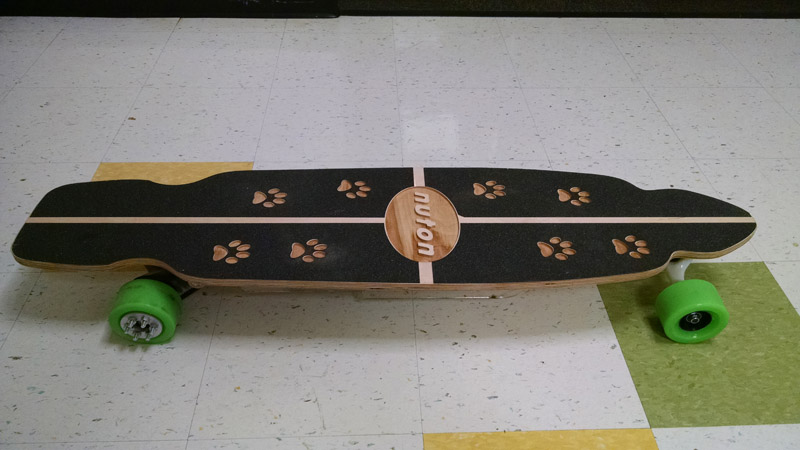
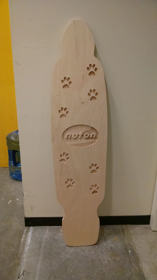
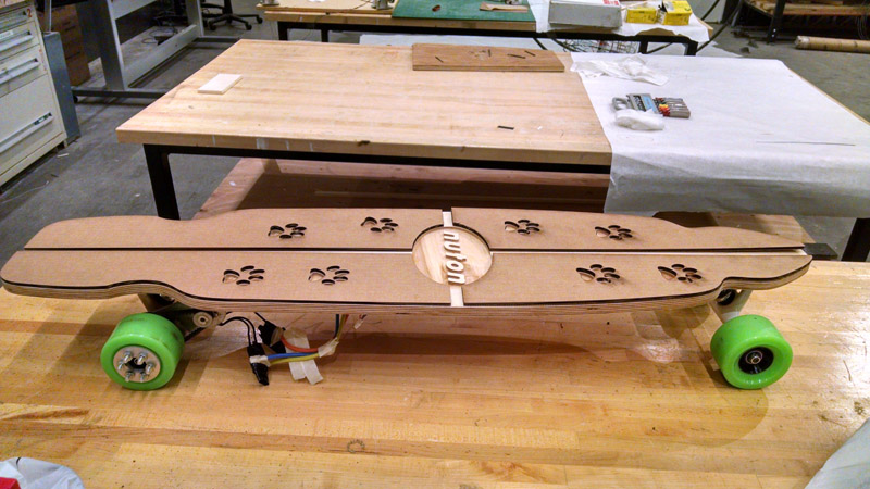
The final deck (after sanding) - looked really nice -
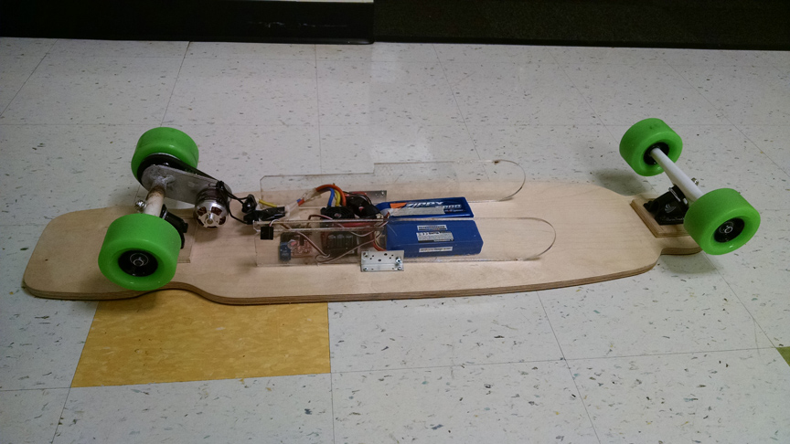
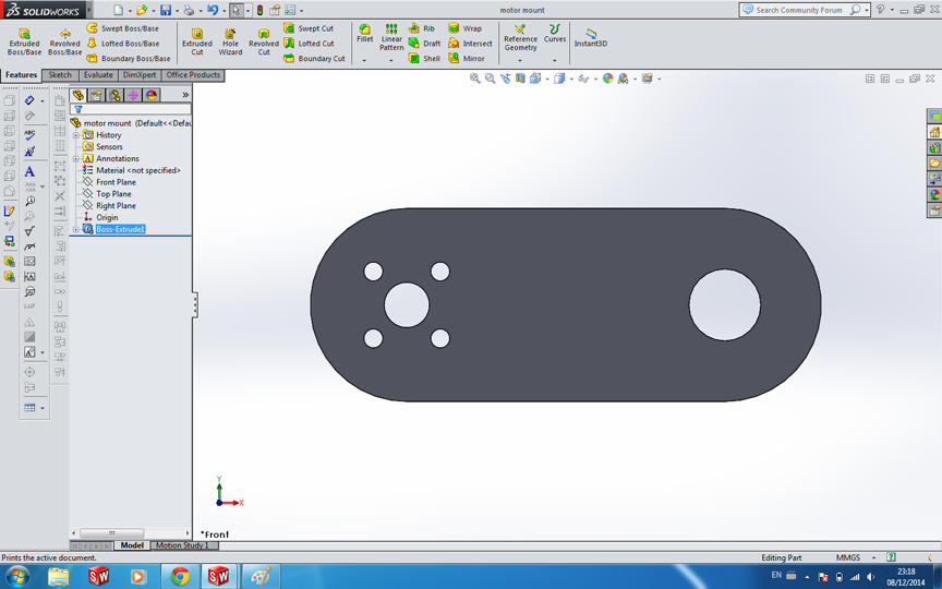
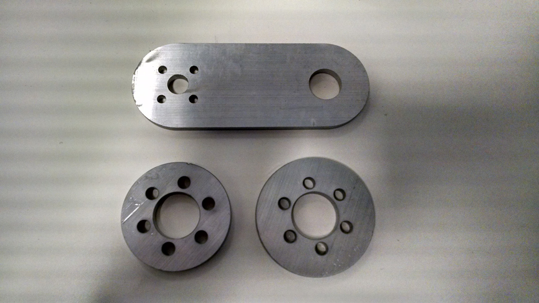
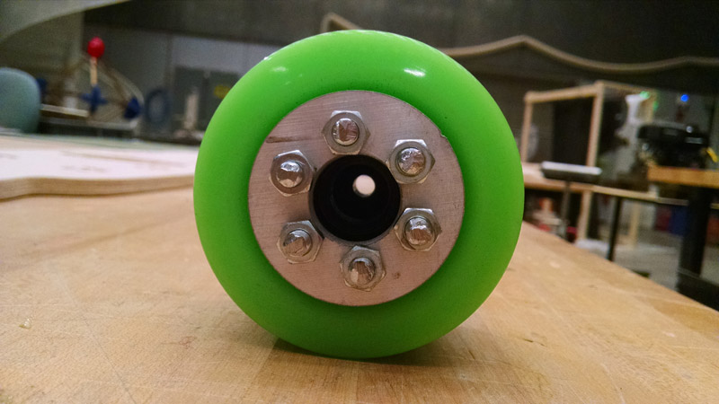
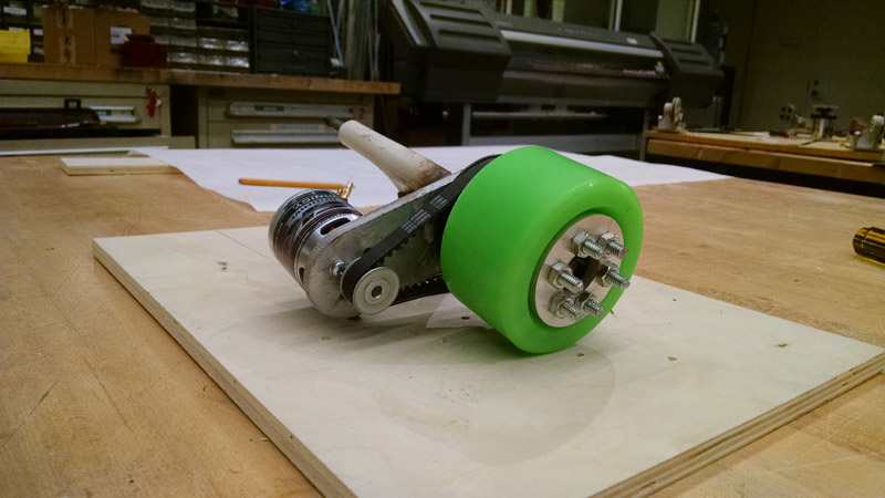
The next step was to model the mount for the motor. This motor mount was designed to hold the motor in place, without interfering with the maneuverability of the board itself. I used 0.25" thick aluminum for the material. Similarly, I used the same material for the wheel's washers.
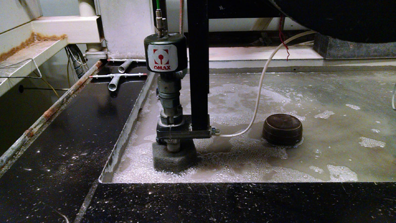
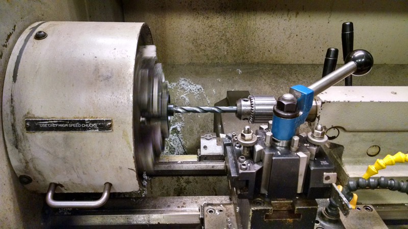
Water-jetting time! John helped me use the machine and cut my pieces to the size of my CAD models.
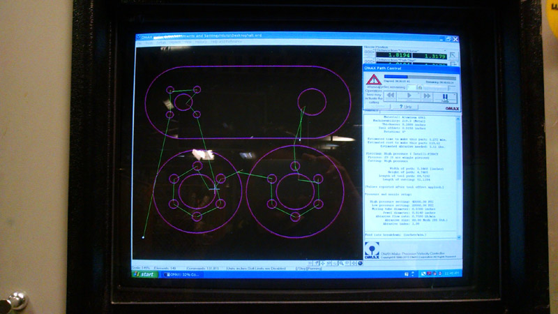
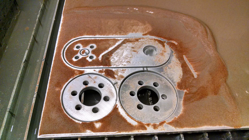
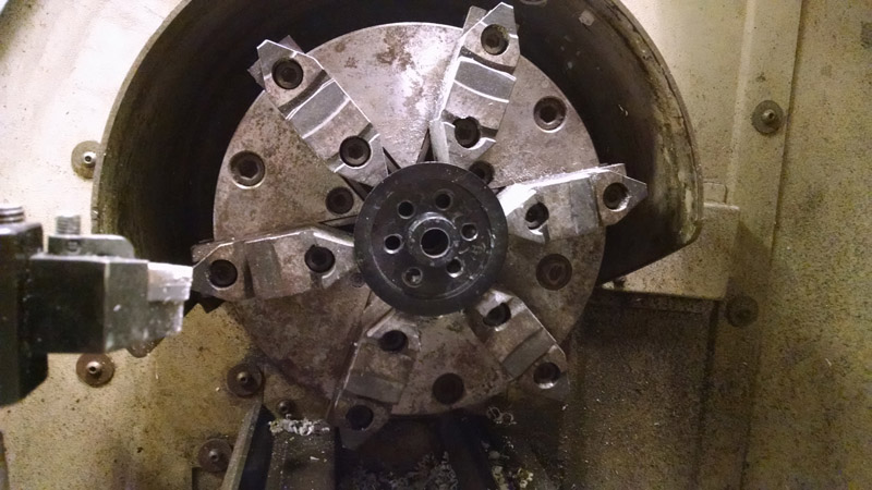
Milling the Motor mount and washers (holds the gears + timing belt)
Fitting the mount before welding.
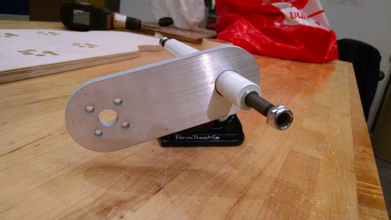
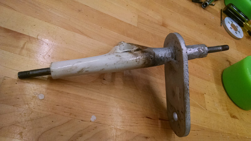
Welding time. With John's help I was able to get the mount secured to the truck.
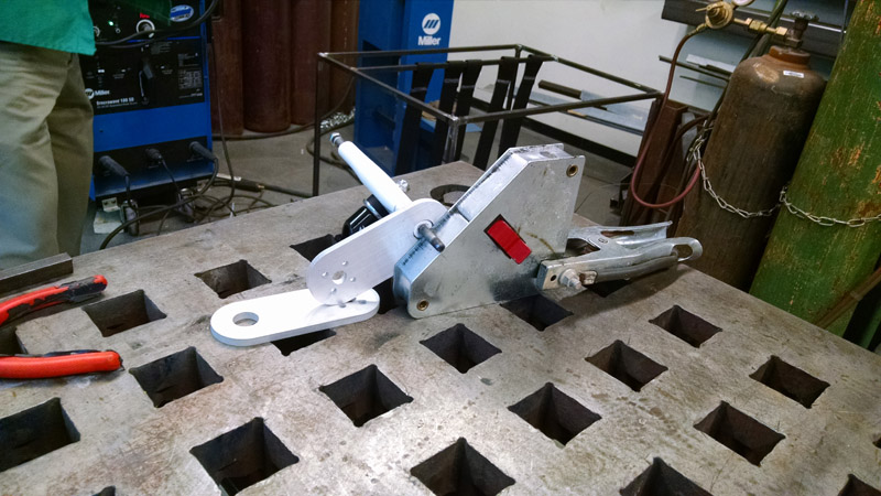
The first welding result seemed okay enough, but after putting the board together, I noticed that the mount was too far out - thus the wheel could not be secured with the nut. Moreover, the drive-wheel was sticking out, making the two wheels assymetric (therefore creating a different torque and shifting the board towards the motor's side).
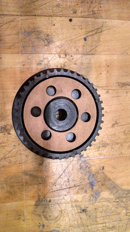
Before retrying to weld, I want ahead and laser cut a template for drilling holes in the gear that attaches to the wheel. I also made the center hole larger so that the wheel could fit onto the truck.
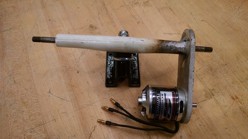
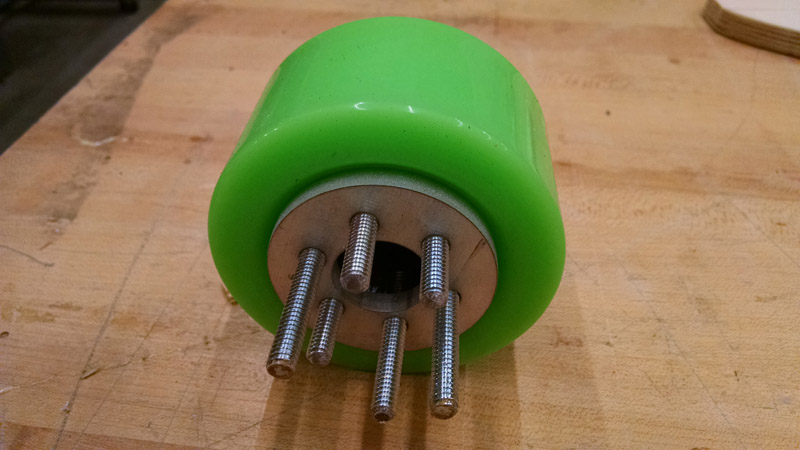
Putting together the wheel, washers and gear.
Finishing touch - clear-coat painting the deck for protection against water.
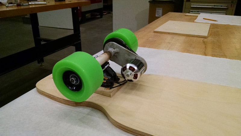
Second attempt - welding and putting the mechanics together. Notice how the mount is now further in.
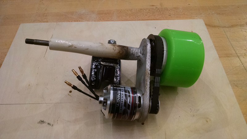
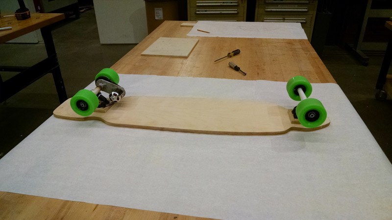
Mount, trucks, wheels mounted on the deck.
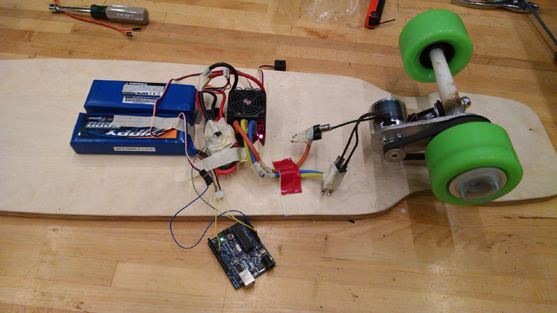
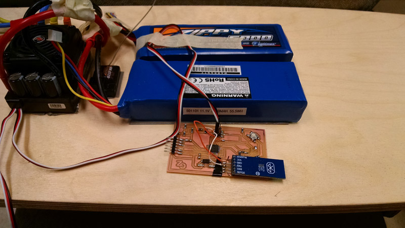
Electronics! Connecting the ESC and batteries to the motor. I chose a brushless motor (common in RC planes/drones) for their efficiency and low weight. Specifically, I used EZRUN 150A PRO, powered by two 3S 5000mAH LiPo batteries connected in series (providing 6S output).
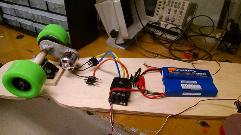
After testing the electronics, V1 of the board was ready.
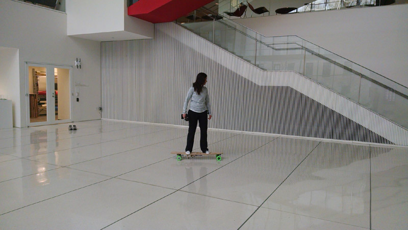
Then it was time to take it for a test ride!
Now it was time to add the magic touch. Until here, I used mostly stock electronics - an ESC controlled by an RC remote.
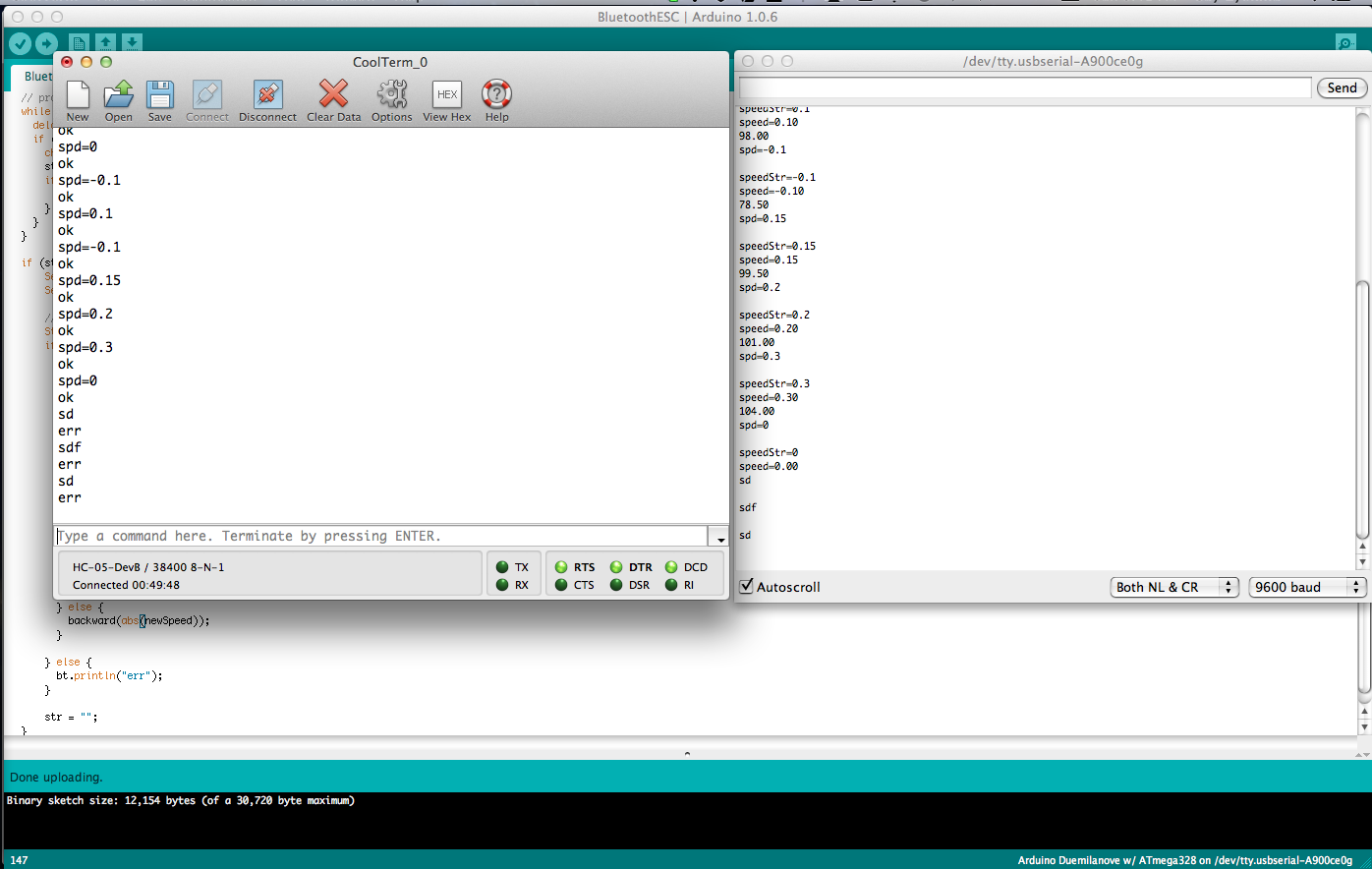
Most RC motors/controllers respond to PWM (or PPM) signal. Starting with this bit of information, I used an arduino connected to the ESC directly, and tried probing how different PWM values affect it.
This was a VERY tedious process. First, the protocol is not trivial at all - the 'Neutral point' (stopped poisiton) is around angular 90 degress (when treating the ESC as a servo). Second, anything lower than 90 degress means going backward, and anything above means going forward. So - forward acceleration means going from 90 and above (to about 140), while forward decelartion is the opposite. However, backward acceleration means decreasing the value from 90 up to 20 (20 being the max speed).
Braking and changing direction was even more tricky. In order to switch from backward to forward, one can simply change the position from less than 90 to above 90. However, the other way around requires going backwards, then forward, then backwards again. The code I wrote for the microcontroller wrapped that functionality.
After several hours, I got the Arduino to fully control the motor!
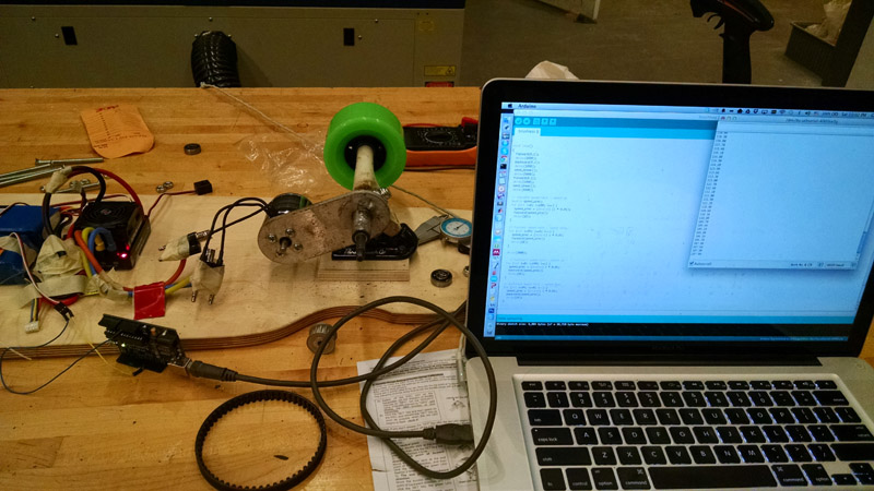
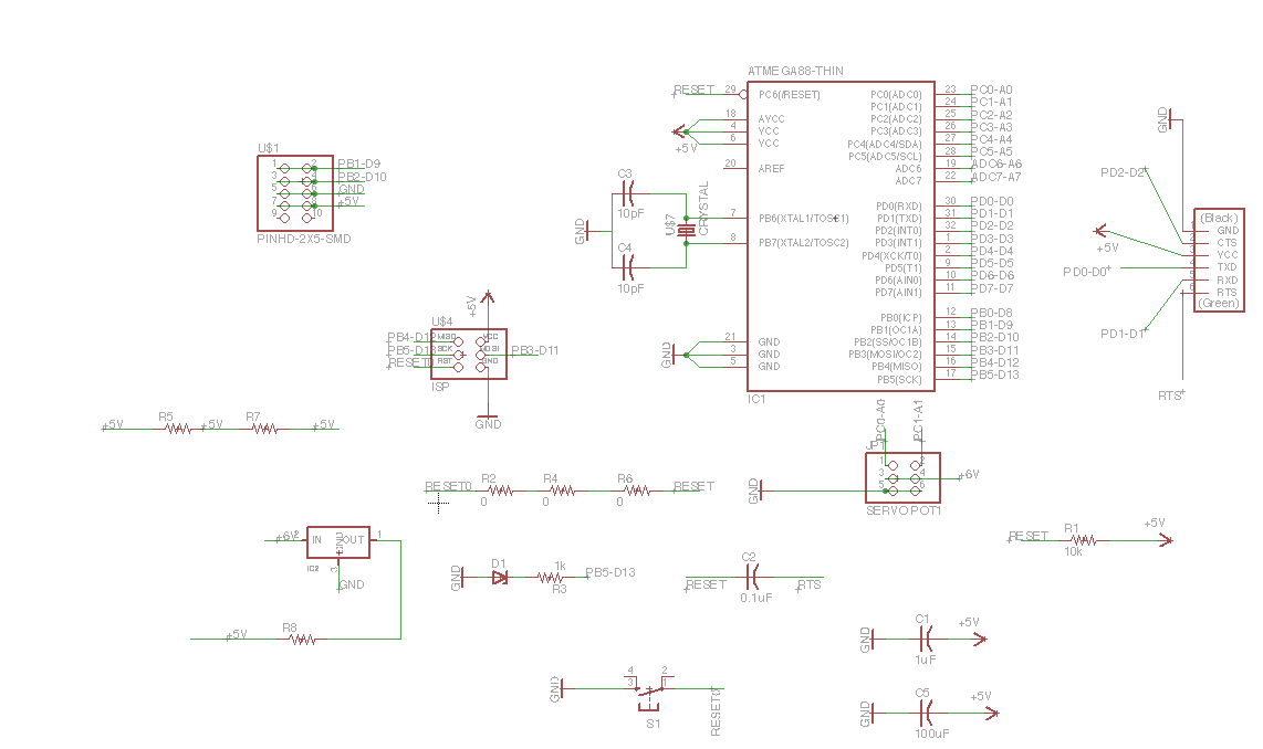
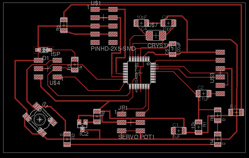
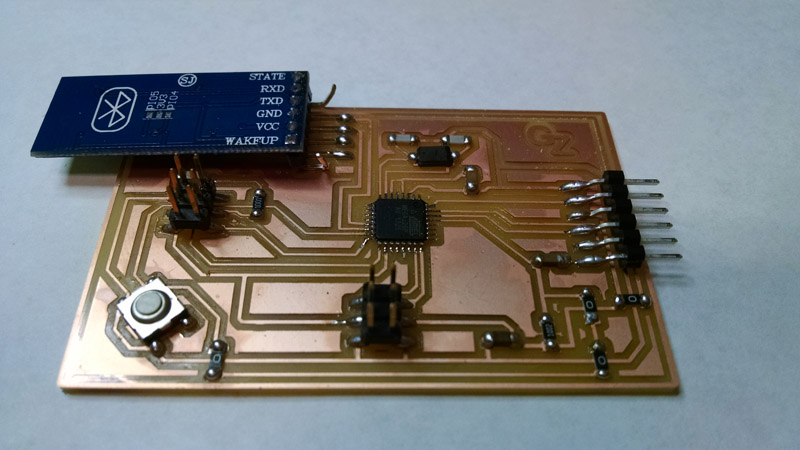
Now that the Arduino was working, it was time to design a custom board. I used our good-old pal Eagle to design a board based on ATMega328P chip. I made an interface of the board for two servos - allowing me to easily connect the ESC to my board like a normal servo. I also routed the leads for the Bluetooth model correctly. I used a pseudo 2x5 header which I then soldered the HC-05 module onto. Please note - the board listed here includes a voltage-regulator, since after milling the board I found out that the ESC supplies 6V for the RF channels. In practice, due to shortage of time, I hacked my milled board and soldered the voltage-regulator on it. This actually worked perfectly, but the design here is cleaner.
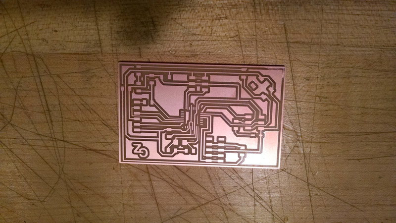
Milling the PCB board
Stuffing it and soldering the BT module.
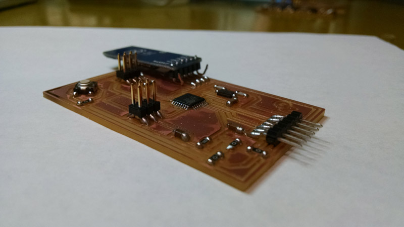
Arduino and annoying breadboard out - custom board - IN!
I added code to support BT communication. I made a simple protocol that supports two commands over bluetooth: RST and SPD. RST should be sent whenever a new user (phone) tries to communicate with the board. This ensures any current state information is cleared. The second command denotes the required normalized speed (0-1 scale). The board itself is incharge of mapping the normalized value to a real angular position.
Finishing touch - laser cutting the grip tape. I used a CAD software to split the original board design into 4 pieces. I then did a first test run using cardboard. This also helped conserving the relatively expensive grip tape material (which I had little of).
Then working with the real stuff - laser cutting the grip tape.
And this gave us the final board (After some cleaning up and creating an initial protection for the electronics). The result of using CAD to cut the grip tape gives an awesome professional look-and-feel!