Week 2 - PCB Production
FabISP ProgrammerFor the assignment this week, we were asked to mill the FabISP - a small-factor board powered by an ATTiny44 micro-controller. The board’s purpose is to be used as a programmer for other custom boards we design.
I decided to start with Valentin’s design, which in my case proved to be more challenging than expected (more on that later).
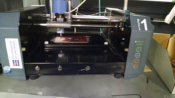
First, I went ahead and milled the board. This process took some time, mainly due to two software concerns:
The device was under /dev/ttyS0, and not /dev/ttyUSBx. Had I bothered to check the desktop’s wallpaper, I would have noticed that immediately. Alas, I spent ~30m and found this solution the hard way, by disconnecting the serial cable from the PC, and then checking dmesg for the newly connected port, which revealed it was indeed ttyS0.
There was a permissions issue when trying to open device ttyS0. To workaround it, one needs to run:
sudo gpasswd --add fab dialout
Eventually, I had the machine working properly. After a couple of attempts, I got the board milled correctly (or so I thought):
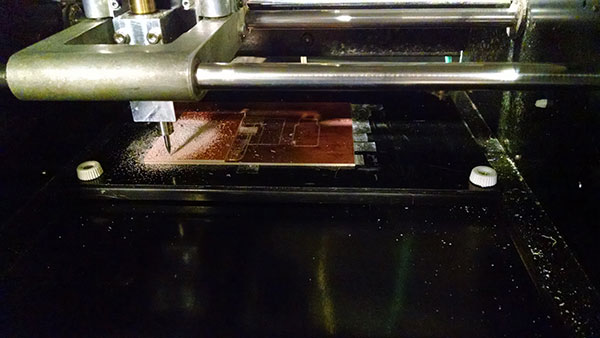
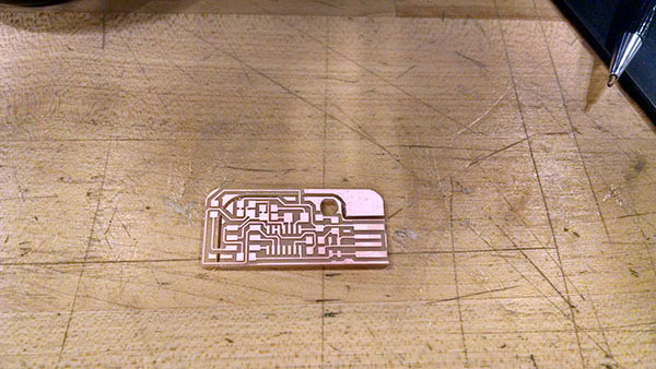
At this point I was really quite satisfied. That is, until I figured out that there are short circuits. It took several attempts, until others had pointed out that changing the ‘tool diameter’ parameter to 0.3 (from 0.4), fixes the problem.
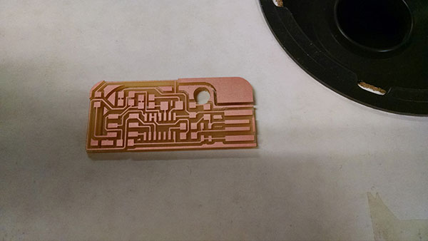
Indeed, that solution worked perfectly, and I found myself (finally!) with a perfectly milled board.
Next came soldering all the parts. It took a little while, and I believe that I eventually found a couple of good techniques that worked for me:
Technique 1:
a. Flux the surface part you’re going to solder.
b. Solder one joint with a larger blob.
c. Hold the component down with the tweezers,
gently apply solder with the tip and wire and let it smoothly flow to the joint.
d. Go back to fix the first joint.
Technique 2:
a. Flux the surface part you’re going to solder.
b. Apply solder to the traces where the joints are going to be soldered.
c. Hold the component on the traces. Underneath the trace,
use the tip of the iron to heat the previously applied solder.
The component’s joint should now be firmly in place and soldered.
The first technique yields better results (the latter might not result with very tight soldering), but takes somewhat longer.
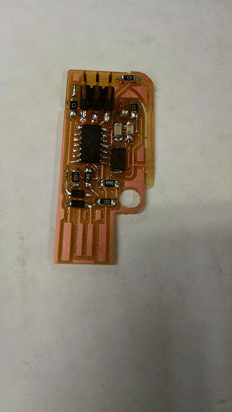
Eventually, I ended up with the soldered board:
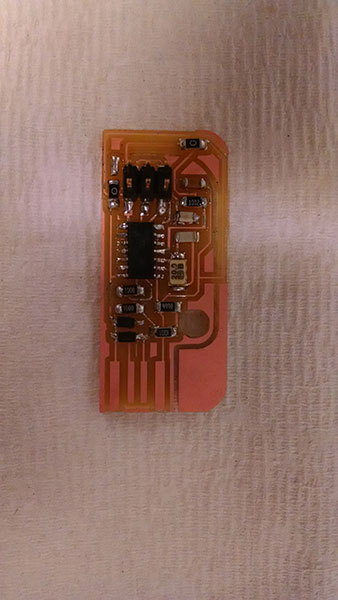
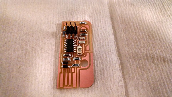
But then I noticed that some of the components were misaligned. I desoldered them and soldered them again properly. Unfortunately, this has made a little of a mess with my board. I was also short in time at this point, since I spent a lot of time making a custom press-fit acrylic box, which I had to eventually abandon about 80% through.
After all the hard work, I failed to program the board. I checked time and again for shorts, but couldn’t find any. Eventually I had given up and simply made the reference board, which was successfully programmed (but the flow wasn’t documented due to cutting it so close to the deadline. However, it’s practically the same).