Week 3 - 3D Printing
(It's not a replicator)This week we learned about 3d printing - what's been the subject of a lot of hype in recent years, and admittedly - one of the things I was excited to play with.
The first thing we learned was that 3d printers aren't really replicators. Not even close. The outcome of the models I designed later on, prove that hypothesis :).
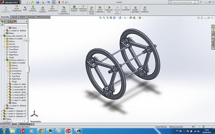
We were asked to design something of our own that could be made subtractively, and cannot be easily made with other fabrications techniques like casting/molding, and then print it. I decided to create a small-scale model of my final project, since I wanted to get a feeling of how it would work. This is especially tricky, since I'm trying to build a type of vehicle, where the cabin/inner frame is free to move with respect to the outer wheels.
After several hours spent on SolidWorks, I was able to design the DiMotor - It has two large wheels, where each wheel has 3 idler wheels controlling the inner frame.
Then, after adding a cabin in the center, I obtained the final model.
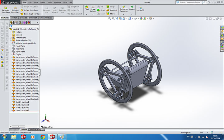
I have kept my model at around 4" on all sides, and as instructed in class, I maintained gaps of 0.015" between the different parts. Unfortunately, the class' TA notified me that a 4" model is too large to print, and had to be scaled down in half. Doing so made the entire construction fall apart upon 3d printing :(.
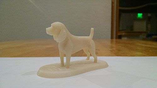
I also wanted to 3d-print something nice, albeit less practical. I found an STL model a beagle, and decided to tweak it to my own liking. This has turned to be significantly harder than I thought. Originally, I imported the STL into SolidWorks, and designed a base unit with the inscribed of my own dog - 'Newton'. It looked perfectly in solid - that is, until I exported it as STL.
Once I did that, I tried to open the generated STL file, and to my surprise - the Beagle model was gone, and all it had was the base unit I designed. Googling suggested that simply importing an STL graphics to SolidWorks doesn't work, as SW ironically doesn't recognize it as a solid.
To work around this, I used MeshLab. I took the two STL files (beagle and base unit) and imported them.
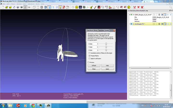
I then applied a translation transformation to 'merge' the two together, which looked great in the modeling software.

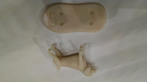
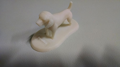
The 3d printed result was less optimal. It seemed like the the two meshes were not printed as a single unit, and the printer thought that there should have been a gap between the beagle's feet and the base. I'm still not exactly sure why this has happend or how to fix this (I imagine it's something to do with the mesh not being closed around the feet due to the way I merged the two STLs, but that's just a guess at this point). Would be interesting to look into it.
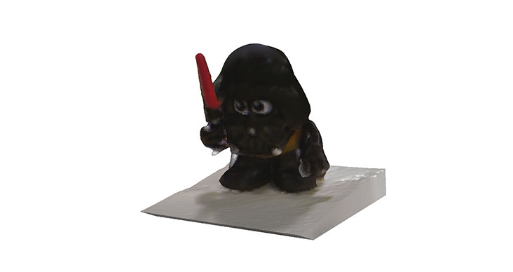
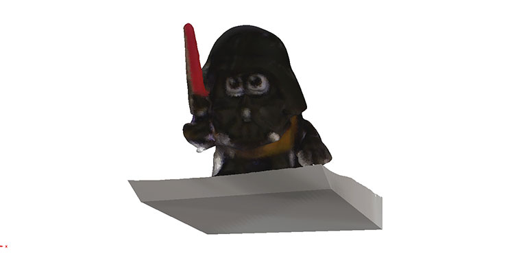
The last part of our assignment was to 3d scan an object. For that purpose, we used the Sense consumer 3d scanner. I didn't encounter too many issues with the scanner, with the exception of being VERY careful when moving around the object while scanning it.
Here's the result of a 3d scanned Darth Vader Mr. Potato Head -