Because my project was not quite successful last week, I tried to catch up this week by doing an input and output device. Unfortunately, I wasn't quite successful this week either. But, all is good. I made a bit of learning progress for the final project, and I understand how to do all the necessary steps for this week (in theory).
My project for this week was directly related to my goal for the final project. For the final project, I want to make pedals for a bicycle that have a pressure sensor on the pedal itself and the toeclip so that the rider can monitor their pedaling in real time. Ideally, this device will be connected to four LCD screens (left/up, left/down, right/up, right/down). I want to make my own pressure sensors, as I tried to play with last week, but I realized this week that the foam I have is non-conductive. So, I decided to use the step response touch sensor as input and then write a program such that an LCD screen reacts when someone touches the touch pad. I figured that once this idea was fleshed out, I could essentially replace the touch pad with a pressure sensor and change the program so that the LCD screen would display the sensed pressure.
For practice, I first just made Neil's hello.LCD board.
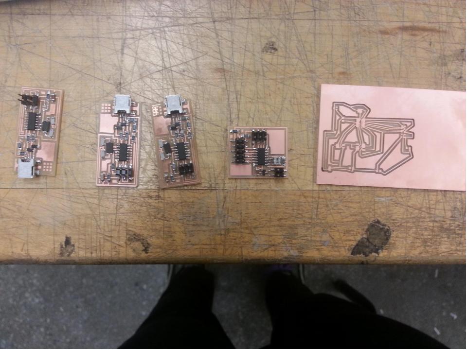
I also made another FabISP. (This is my fourth? one). Here's what a few non-functional FabISP's in a line look like (plus the LCD board).
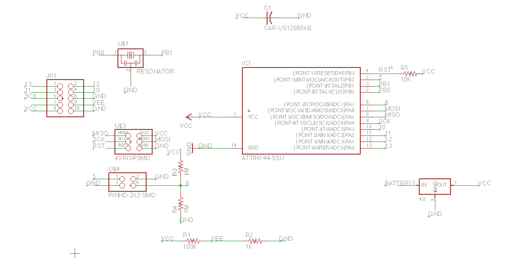
Then I took a look at the step response board. I used Eagle to combine the two boards and I found Diego's page from last year to be a little bit helpful. The main change I had to make was the decision about the power source. In the hello boards, the power source is from an FTDI cable, but because I want to get this to be portable I decided to set it up for batteries. So, I kept the 5 volt regulator and then set the VCC-in to be from the battery. I removed the FTDI piece entirely. For this purpose, the 5-volt regulator is probably also decently unecessary. The LCD spec-sheet indicates that it functions between 2.7 and 5.5 volts. AA batteries output about 1.3 volts, so three or four batteries would be sufficient for this week's device. After playing around in Eagle for awhile and then getting some advice from a TA, I had this schematic:
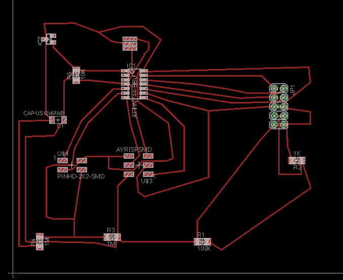
Then I switched to the board view and began to route the board. I had a lot of trouble getting it to follow the design rules and reach everything it needed to reach. I edited it a bit in Paint as well to get this result:
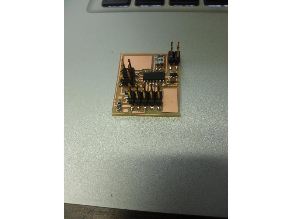
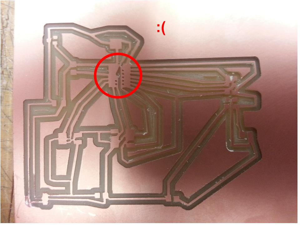
I output this board from Eagle at 500 dpi. When I uploaded it to the fabmodules, it was larger than the copper board size, so I changed it to 700 dpi. I then milled this board. Unfortunately, I think messing with the resolution messed up the trace a bit, and the board came out like this:
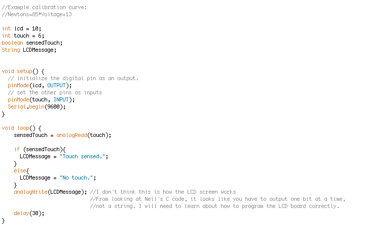
I then focused my attention on the programming. Logically, I would have to set the touch pad as an input pin and the LCD screen as an ouput pin. The input is binary (being touched or not) and so I would then define two corresponding output states. If the pad is being touched, the screen displays "Touch sensed." If not, the screen displays "No touch."
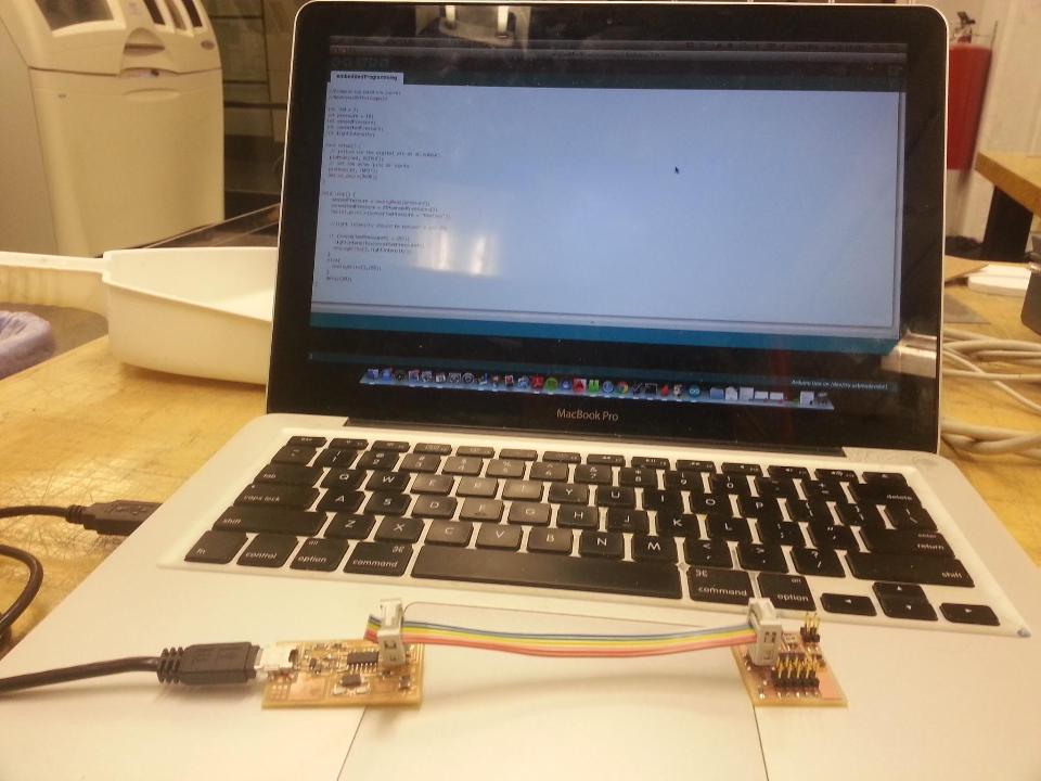
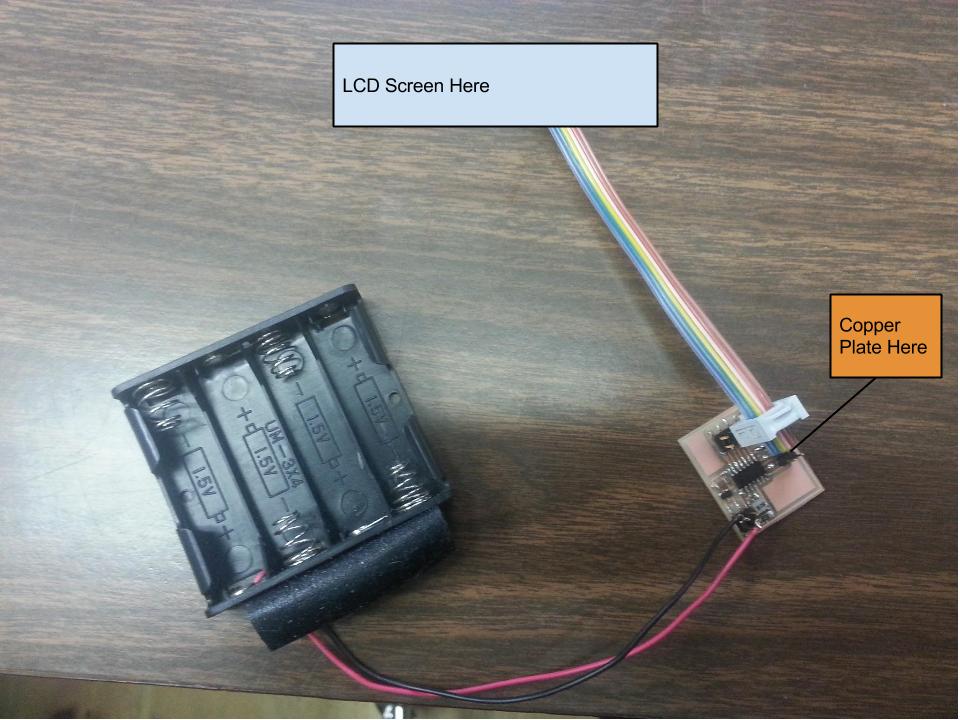
Now that this code might work, it would be great to test it. I found out that our lab section does not have LCD screens. So, I have just set up how configure the hardware for programming and then for use.
Looking at Neil's code, I'm pretty sure I went about programming incorrectly. It looks like each character needs to be sent rather than a string.
I am finding debugging to be a real test in patience. Because of my schedule, I can't devote much more than 14 or 15 hours per week to this class, but sometimes debugging just wastes a ton of time. It's super possible to spend a lot of time accomplishing nothing. For this reason, I've been using the past few weeks to make sure I understand how to do everything and then attempt to do everything. However, I've been doing pretty poorly on actually getting everything to work as it is supposed to work. Hopefully it will all come together with the final project.