
Assignment 10: Electronic Outputs
This week was all about running output devices from a microcontroller. For my final project, I want to get GPS data from my phone to a microcontroller, to drive a servo for a clock hand that shows my location. So to plan ahead for that, this week I decided to design a board that can drive a servo, but can later be used with a WiFi shield as well. Over the summer, I'd bought a WiFi Shield from Adafruit, that I'd originally planned on using with an Arduino. However, for the class, I decided I'd use the WiFi Shield, but I'd make my own microcontroller.
Designing a Fabduino
I spoke to Will, our TA, about this a bit, and he was worried that because all the libraries for the WiFi module are made for an Arduino and not an ATtiny44, it might be more difficult for me to program. Enter the Fabduino! With the Fabduino, I can program the WiFi shield as though it's attached to an Arduino. There's already some great documentation online, including The Fabkit, Neil Gershenfeld's board, and this handy tutorial on using a Fabduino with a servo! The documentation on the WiFi Shield also lists which pins the shield uses from the Arduino.
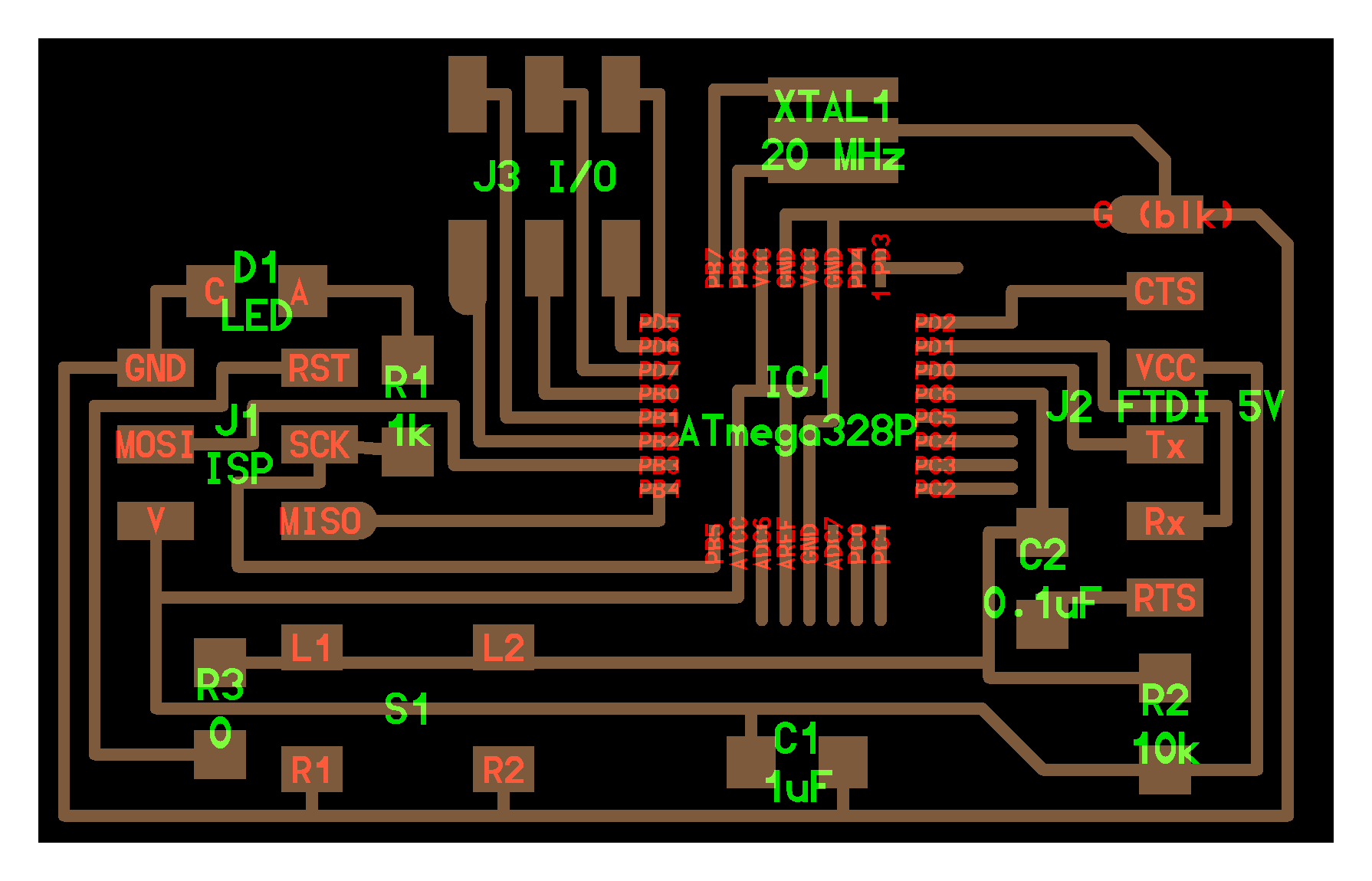
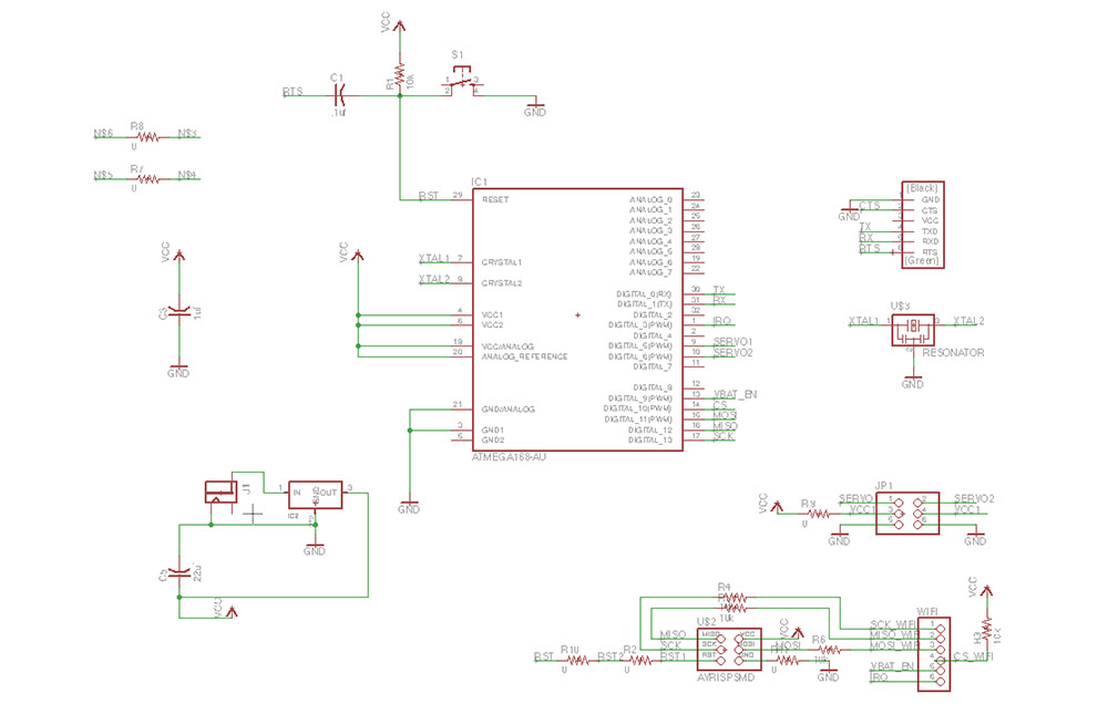
For designing my own board, I needed to make some modifications to the existing boards:
- Removing the pins I wouldn't need for the servo or WiFi Shield. (I left an extra set of pins for a second servo, in case I decide to add another clock hand later on)
- Adding a voltage regulator and a power jack for external power
- At Will's recommendation, adding resistors to the MOSI/MISO/SCK pins that will be used by both the ISP programmer and the WiFi Shield, and a pull up resistor to the CS pin. I haven't tested the WiFi shield yet to make sure it works though.
- I used an ATMega328p on my board rather than the 168, since that was in the inventory. I've also temporarily used a 20MHz Resonator, but I intend to switch it with a 16MHz Resonator when they become available.
- For the next version, I plan on using a 2x3 header for the WiFi connection rather than a 1x6, since we don't have those available in the lab.
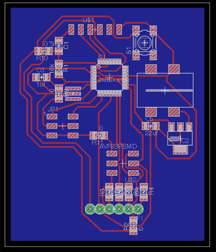
The final design for my board is below. I removed the indicator LED since I had a lot of difficulty routing the board otherwise.
|
|
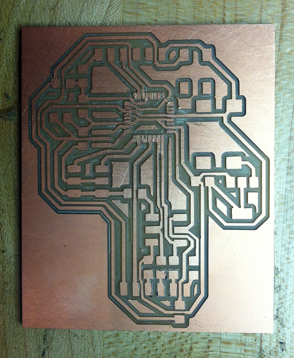
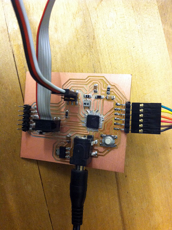
Fabricating the Board
I fabricated the board on the Modela as we've done for previous projects. However, for the ATMega328p, the traces are much closer together. I wound up cutting those traces manually with an exacto knife. However, what I didn't realize until after I spoke to Charles was that there were smaller end mills available. I will try using that for the next iteration of the board, since I had a lot of difficulty cutting the board manually. I wound up both testing with a multimeter to make sure the traces weren't still touching, and even removed the ATMega to get in with an knife again.
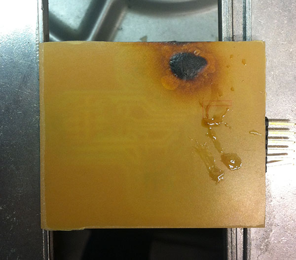
One thing I that I misunderstood was how to remove parts using the heat gun. For whatever reason, I remembered from class that we were supposed to use the heat gun UNDER the board rather than over it. Don't do that. There isn't copper to dissipate the heat, it just burns.
Programming the Board
To program the board, I followed the Fabkit tutorial, with a few changes to get it to work. The first was modifying the boards.txt file for use with the ATMega328p. The second was using AVRISP mkII as the programmer, and not the USBTinyISP. Then, I went to File-->Upload Using Programmer, rather than just uploading as usual. For the time being, I relied on the internal clock, until the 16MHz resonators arrive.
I ran a simple Hello, World program in the Serial Monitor which worked just fine! Then I plugged in a servo and ran a very simple program on the Arduino to test that it can successfully go to the programmed angle. And it worked!
My goal next week is to attach and test the WiFi shield, and use it to tell the servo which angle to go to. For the actual clock, I'll probably use a 1:2 gear to change the 180 degree angle of the servo into a full 360.