
Assignment 7: Program a Microcontroller
Our job this week was to read over the datasheet for the ATtiny44, and to program our microcontroller. Unforunately, this week I didn't have as much time to devote to the class as I would have liked, so while I did manage to program the microcontroller, I didn't have the opportunity to do anything particularly exciting.
Programming in C
First step was connecting the FabISP to the microcontroller, using the ribbon cable. The first time I did this, I was dismayed to find that my computer no longer recognized my FabISP, which had already been programmed. I spent a long time trying to figure out what went wrong when I realized that a resistor had fallen off my board. I soldered it back on, but the board still didn't work. I wound up making a new board, which worked fine.
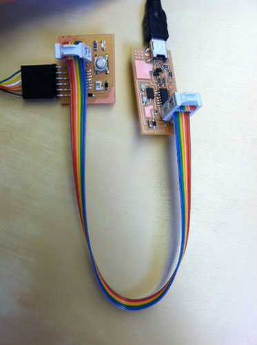
Next, I tried connecting the microcontroller to the FabISP and programming it with the echo program in C, using emacs as my text editor. I followed these instructions. This mostly worked. However, for whatever reason, somewhere between the board and the connection with my computer, it didn't seem to get the interrupt signal. So rather than waiting for me to type before echoing back, it continuously sent a signal saying I'd typed nothing.
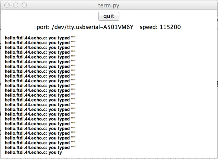
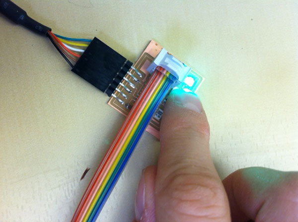
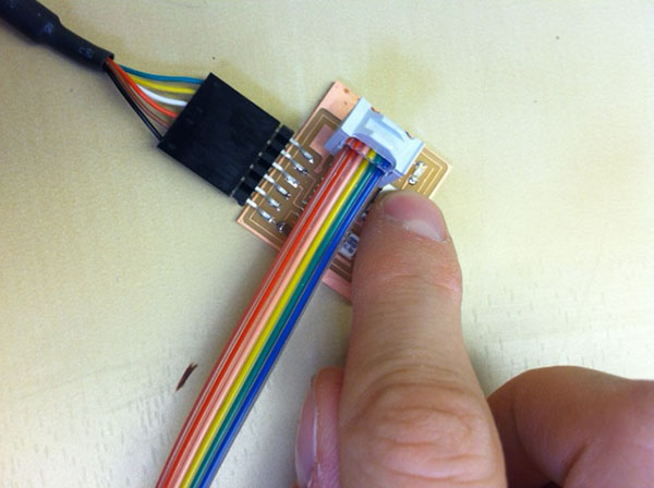
Prashant (our TA) and I spent a really long time trying to figure out what was the problem, but never got it working entirely. (When we tried using the hello.ftdi.44.echo.make.interrupt.c file, the terminal monitor showed nothing at all). In the interest of time, we decided to make sure we could at least do something basic like make a blinking LED. For this we used an existing program that was written for the class.
//
// hello.RGB.45.c
//
// RGB LED software PWM hello-world
//
// Neil Gershenfeld
// 11/10/10
//
// (c) Massachusetts Institute of Technology 2010
// Permission granted for experimental and personal use;
// license for commercial sale available from MIT.
//
/*blinking_led.c
*
*This code blinks the LED D2 on PORTB PIN6 i.e PA7 of the AVR board.
*
*The LED D2 is connected to PA7 on the Atmel chip, and is wired so that
*it will be ON when the output is high and OFF when the output is low.
*
*The "special function registers" used in this program are:
*DDRA -- Port A Data Direction Register
*A high (1) value indicates output, low (0) is input.
*We set the 7th bit in DDRA to configure the PA7 pin as output pin.
*PORTA -- Port A Data Register
*This is used to set the output value for each of the
*eight port A pins.
*WaitMs() is used to produce a delay.
*/
#include
#include
#include
/*Macros definition*/
#define BIT(x)(1 << (x))//Set a particular bit mask
#define CHECKBIT(x,b) x&b//Checks bit status
#define SETBIT(x,b) x|=b;//Sets the particular bit
#define CLEARBIT(x,b) x&=~b;//Sets the particular bit
#define TOGGLEBIT(x,b) x^=b;//Toggles the particular bit
void WaitMs(unsigned int ms);
int main(void)
{
SETBIT(DDRA,BIT(7))//Sets Direction of 6th pin of port A as output
while(1)
{
SETBIT(PORTA,BIT(7))//Sets PORTA7 as high i.e. turn on led
_delay_ms(200);
CLEARBIT(PORTA,BIT(7))//Clears PORTA6(PA7 pin goes low) i.e turn off led
_delay_ms(200);
}
return 0;
}
The original code also included a WaitMs() function to set the time between blinks, but since my clock was set at a different frequency than the function operated at, it didn't work properly. So I replaced that with a _delay_ms function, which is already built into the library.
Programming with the Arduino IDE
I didn't manage to get the echo code working after a bit longer of messing around with it (I'm not sure if the problem is with term.py, or my board, or some interface between my computer and the board). But I wanted to see if I could get the Arduino IDE up and running with the ATtiny, since I'm a lot more familiar with it than with C.
I followed this helpful tutorial from High-Low Tech at the Media Lab. With that, and I was able to get the Blink Sample Code and the Button Sample Code working (but make sure to change the input and output pins).
|
|
What I wanted to get working next was the Serial Monitor. Unfortunately, due to my time constraints this week, I wasn't able to get it running, but from what I gather searching online, you need to get the SoftwareSerial Library running since the ATtiny44, unlike an Arduino Board, does not come with the serial built in.