Project 07
Embedded Programming
This weeks assignment was to become intimate with this document and program our ATTINY44 to do something, literally anything (that we intend it to do :). At first I seemed satisfied to get the board to talk to the computer, show it could blink, and respond to the button press… Then I started thinking, maybe I can go a step further. Sadly, this step is not yet complete, but now I am committed, so I have to finish. Below I will walk through the well documented process of getting the blink-button board running some simple code, and then show some of my progress on a soon to be ATmega328 8-pin Charlie-plexed MIT Media Lab LED logo generator. Yup, you guessed it. A simplified logo means 8 pins is all I need to create all possible Media Lab logos (hmmm, I wonder if I could use even less due to the patterns that arise in the logos… a question for another time or dimension). Either way, logo generator on its way (I think it requires too many vias or jumpers to be functional on a FabPCB, but a great opportunity for me to order a PCB and test the process out).
I started with this tutorial (which covers most everything except the FUSES! so don’t forget to set them :)
Before programming the chip, we first have to make sure we have the hardware setup correctly, and also make sure that we have the proper tools installed on our computer to talk to the chips (FabISP and other board).
Install needed libraries
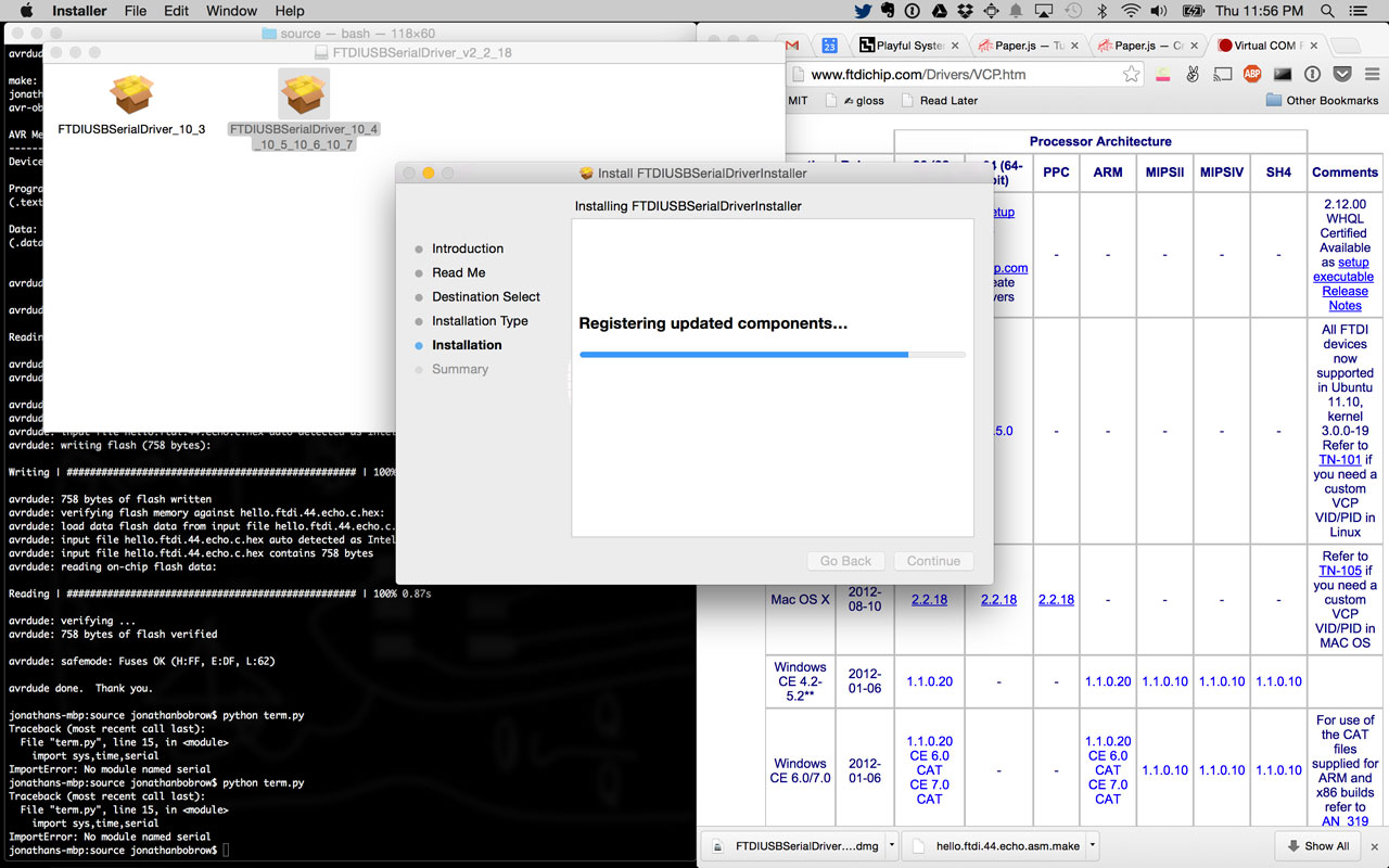
For the python application to talk to the board via serial communication, you will need to install two libraries on top of having Python 2.7 installed. You can install the libraries by calling the following commands in terminal.
sudo easy_install requests
sudo easy_install pyserial
Are you curious what FTDI is? well it is a chip programmed specifically to simplify USB communication to old fashioned serial communication. Since USB communication requires a bit of overhead on the chip (there is only so much space on these small chips for programs), FTDI is a good way to save that space. That is the best justification I can give, it seems as though it is handy for DIY, and less so for production run products.
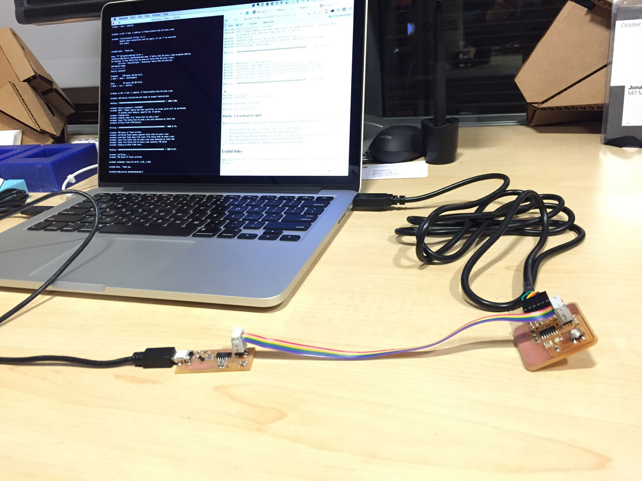
Connect boards
Make sure you connect the boards correctly, ISP headers and the FTDI cable. Getting any of these connections incorrect, 3 in total, could make it impossible to program your board. My first hookup I had the ISP cable backwards, and then I realized I also had the FTDI Cable backwards. Nothing burnt or got ruined, but definitely got me to look twice next time. Also note: a quick way to tell if you are hooked up correctly is to follow a trace to GND or VCC and make sure that lines up with the GND or VCC on the cable you are attaching.
Program Hello World
Generally one would start with a Hello World application, but in this case, the serial communication was that simple application. Surprisingly, the application compiled and programmed to the board just fine and testing it with the python app proved the board could successfully communicate over serial using the FTDI cable. To put the simple C application on the ATtiny44, navigate to a folder containing the C file as well as a the make file. in terminal, make the following calls.
make -f <name_of_application>.c.make
make -f <name_of_application>.make program-usbtiny-fuses
make -f <name_of_application>.make program-usbtiny
In my case, the first application name was “hello.ftdi.44.echo”
This is a handy reminder png of the 3 needed calls
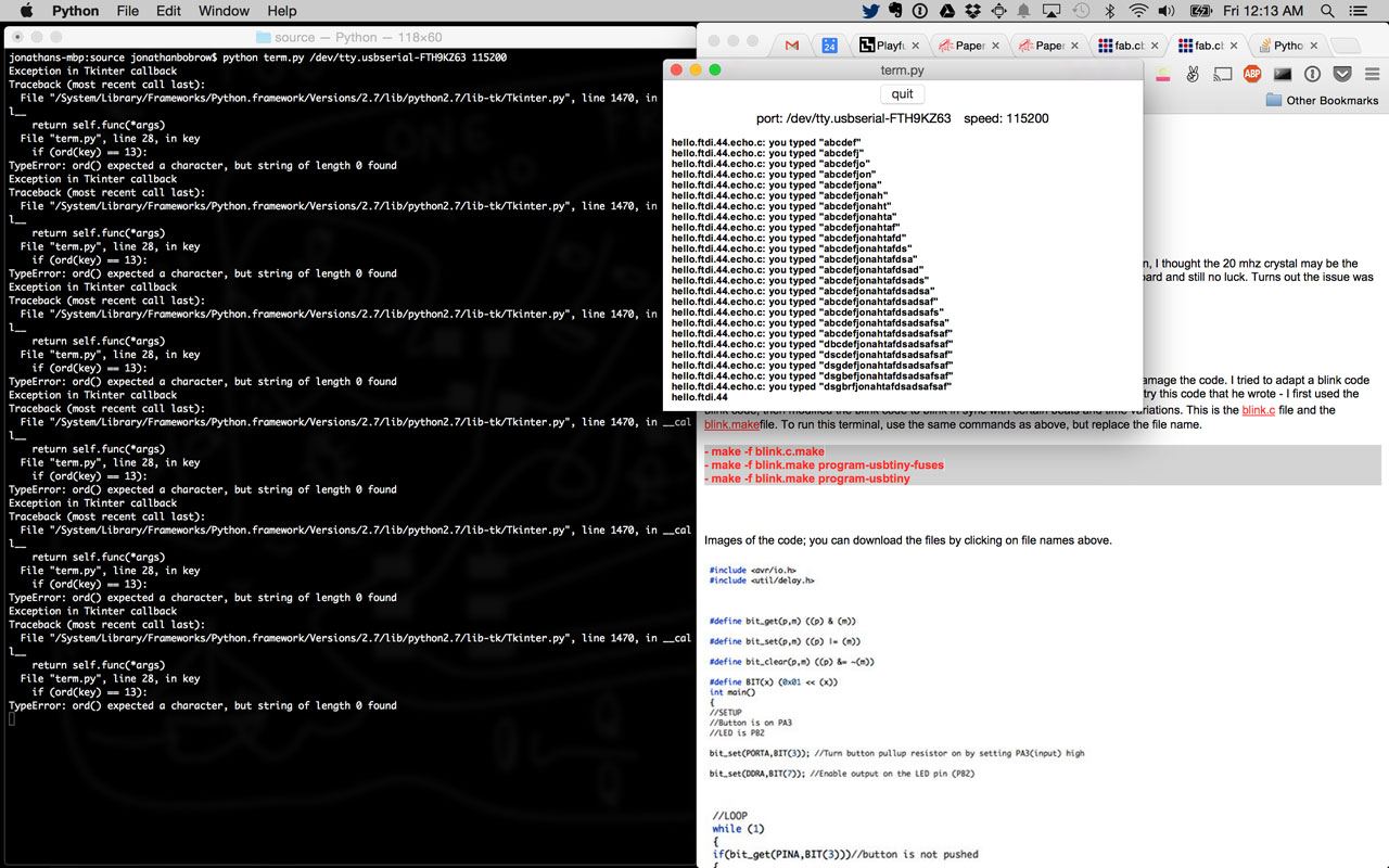
Once programmed, disconnect the FabISP, but leave the FTDI connected to the computer and the newly programmed board. Run the python application, being sure to give it the appropriate parameters.
python term.py /dev/tty.usbserial-FTH9KZ63 115200 (the usb serial will auto complete by pressing tab after the ‘.’)
Also, the python app doesn’t like to quit nicely, so I used Control + ‘c’ to exit the application.

Understanding the microcontroller
A great piece from Greg Borenstein explains a lot of the nitty gritty, starting from Arduino and breaking it down to understand any microcontroller. This definitely came in handy to get me interested in starting a file from (almost) scratch. It was helpful to have a C file with nearly nothing and then build up slowly by creating macros as necessary (as opposed to just taking them for granted as I do with Arduino’s libraries). My code started out like this. Simply setting an LED pin to blink.
#include <avr/io.h>
#include <avr/delay.h>#define blink_delay 10
int main(void)
{
DDRA |= _BV(PA7); // Enable output on LED pin 7// Loop
while (1)
{
PORTA |= _BV(PA7); // turn LED on
_delay_ms(blink_delay);
PORTA = 0; // turn LED off
_delay_ms(blink_delay);
}
}
For now, I prefer seeing _BV for the bit value of the pin, and I don’t feel the need to rename _delay_ms… I think that some macros are handy, i.e. the set and clear seem like the most readily handy, but even still, it is nice to get used to seeing the actual comparators to become more fluent.
Charlie-Plexing
Initially I was planning on using 14 pins (7+7) to get a row/column scanning grid array of LEDs to display the logo, but then Che-Wei mentioned a little thing called Charlie-plexing. There went my night, and here come some links for how I learned more:
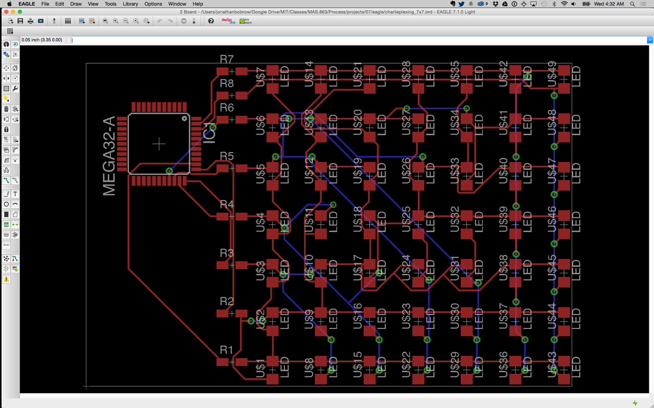
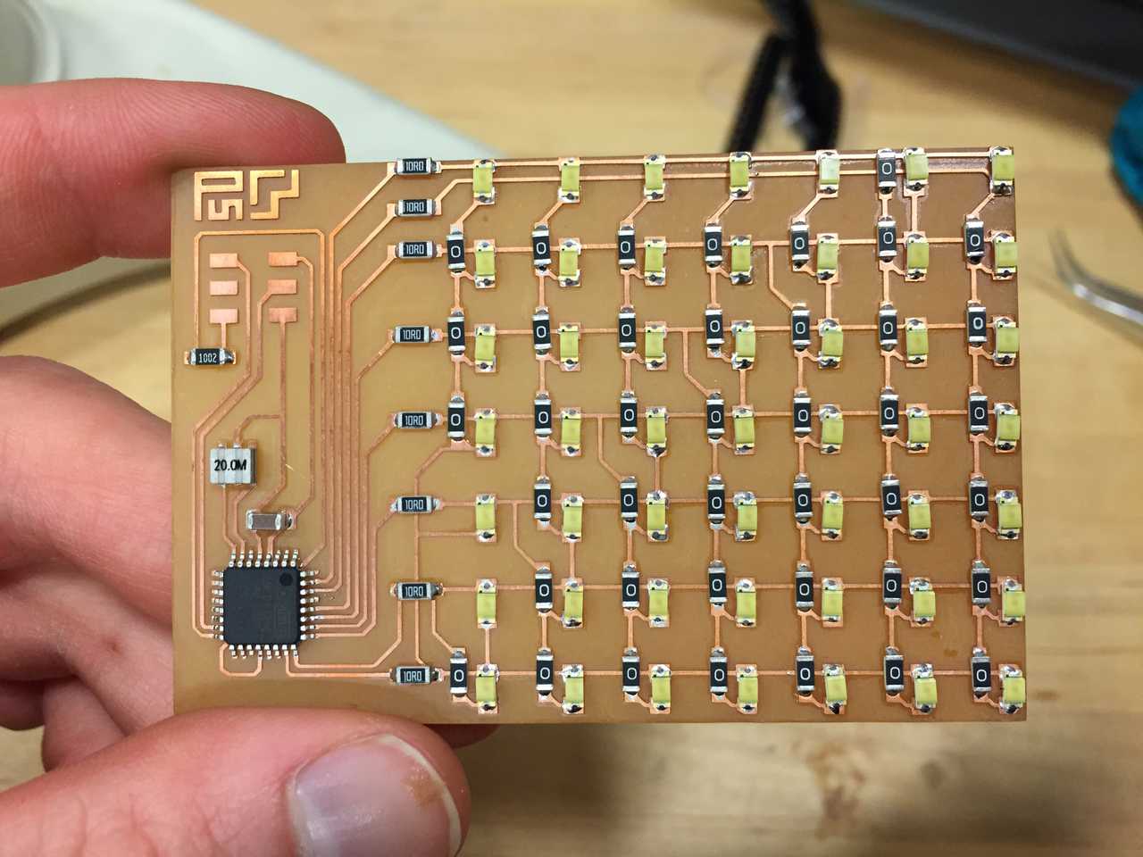
My 7 x 7 Schematic

My 7 x 7 Board