Final Project
Final Project – Smart Dice
what does it do?
When rolled, the dice report their orientation and the value of the roll when determined.
who’s done what beforehand?
what did you design?
- Almost everything :)
- but seriously…
- Form
- Software
- Embedded Software
- Circuit Design
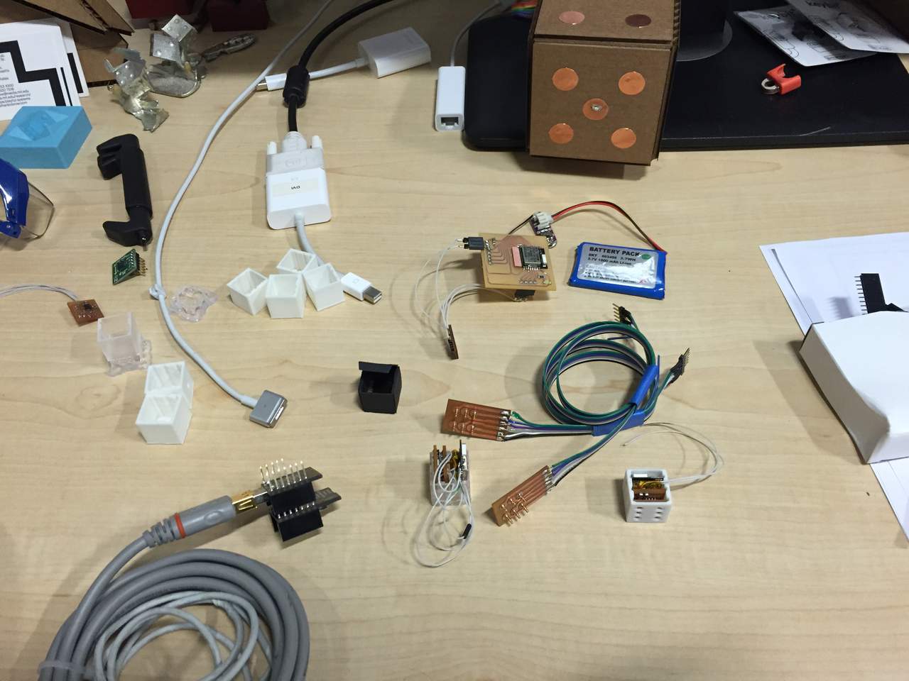
what materials and components were used?
where did they come from?
- Digikey – pins
- Sparkfun – accelerometer
- Adafruit – batteries
how much did they cost?
- RFduino $14
- Accelerometer $4
- Charging circuit
- Resistors
- Capacitors
- LEDs
what parts and systems were made?
- 3D printed case
- Custom PCBs
- Accelerometer
- Charging circuit
- Programming spring board
- iPhone app
- C-code for RFduino
- Mold for charging base
what processes were used?
- CAD – SolidWorks, Rhino, Illustrator, Eagle
- Software – Xcode, Arduino
- Fabrication – FormLabs, Makerbot, Epilog Laser Cutter, ShopBot
- Soldering – solder paste, incredibly still hands :)
what questions were answered?
- For me, this was very much an exercise in limits of size. While many of the components were small enough to fit in a package, ultimately some more system design for connections would have helped make everything fit and work together.
how was it evaluated?
- We are about to find out!
what are the implications?
- No more small stuff. Okay, I will still make small stuff, but with a little more planning.
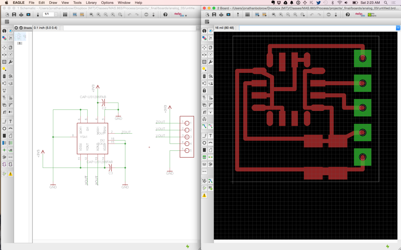
Schematic and board design for the MXR9150 analog 3 axis accelerometer. Contained in a 15mm x 15mm footprint.
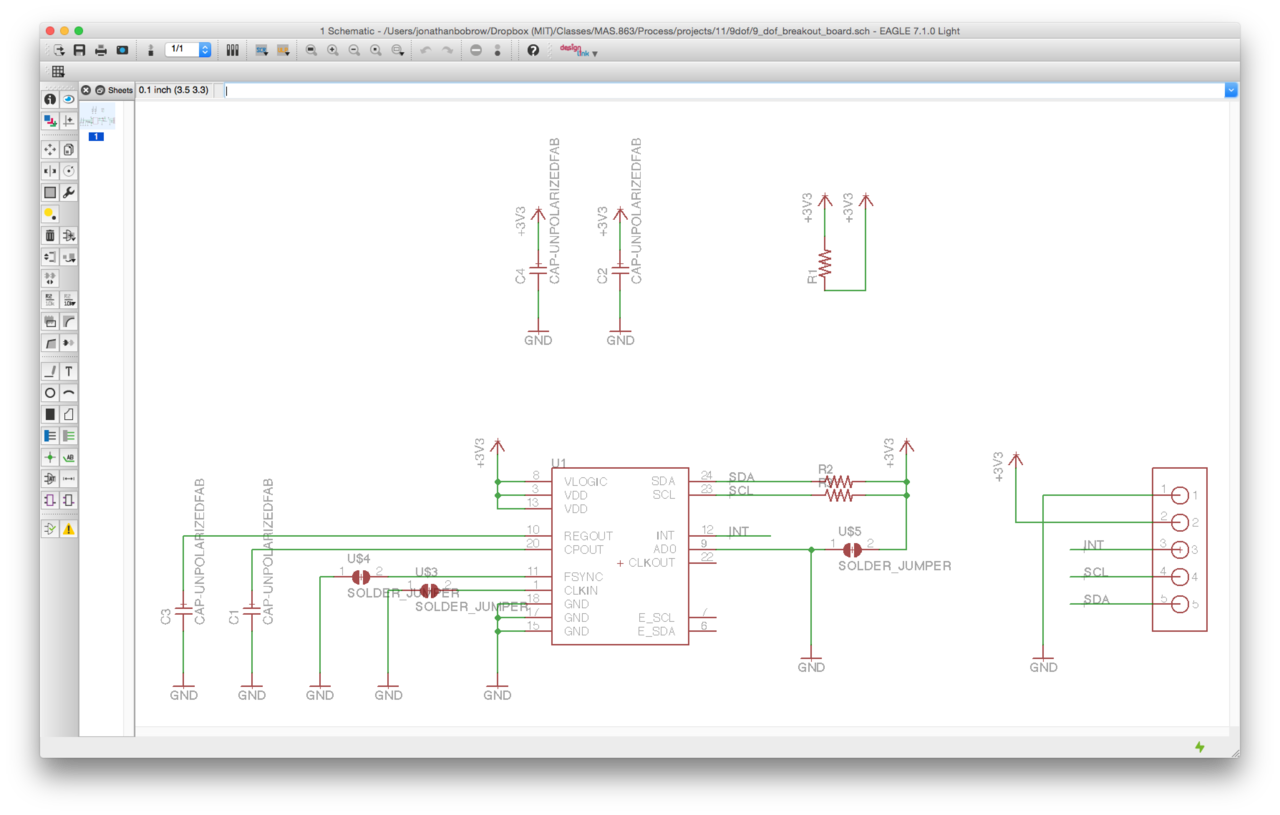
Schematic for a 9-dof accelerometer, gyroscope, and magnetometer to communicate via I2C. Invensense MPU9150. I would later realize that I accidentally ordered the MPU-6150, a 6-dof chip over I2C that is quite similar in pin layout with couple of critical differences.
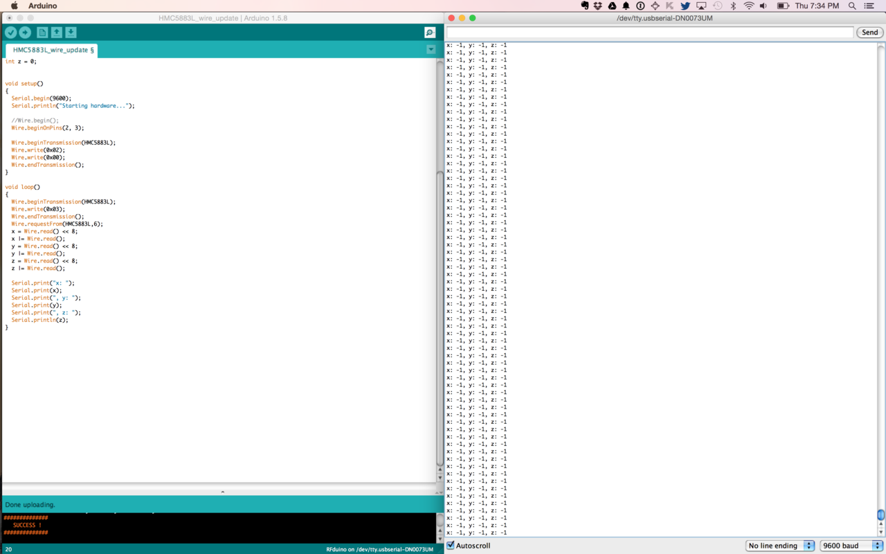
Testing the wire library to communicate with a 3-dof acccelerometer over I2C. Sadly the results given were values not in the range expected. The chip used was the MMA8452, and instead of continuing to work with very small part sizes, I decided to move on to an analog accelerometer, using one more pin, but also saving me the headache of debugging a much more complex integrated circuit.
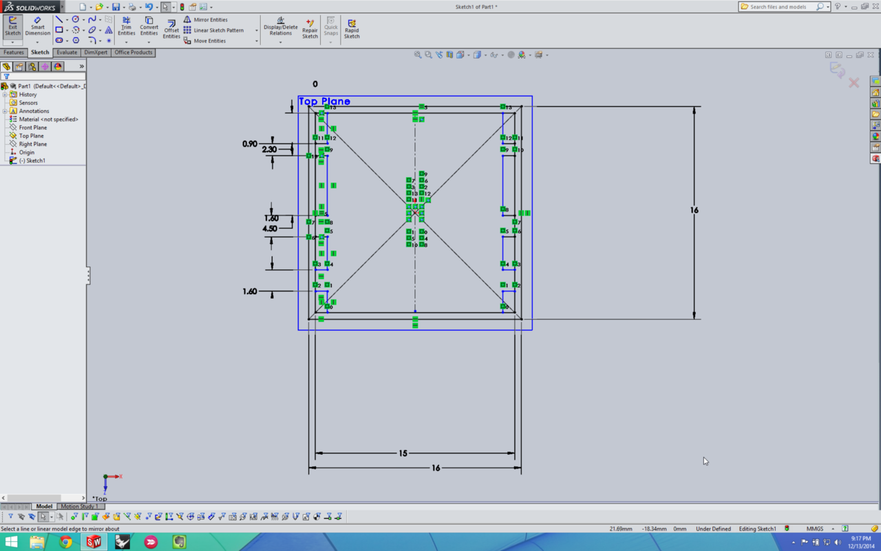
This semester I planned to learn SolidWorks, which I spent very little time in, often coming back to Rhino, which was my new hat acting as old hat. To make shelving for a part that I would print and iterate quickly with adjusting sizes, it made too much sense to use SolidWorks, so I did it. I feel slightly more comfortable with the application and was able to print a series of cases that each got me closer to a perfect fit. Parametric modeling is definitely useful, I simply wish the interfaces to using these tools become more intuitive.
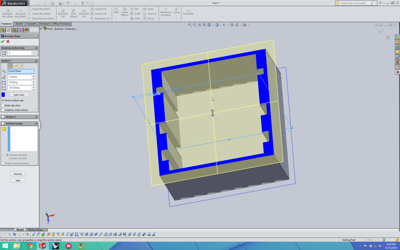
A cross section of the die, showing the shelves which will hold the circuit boards.
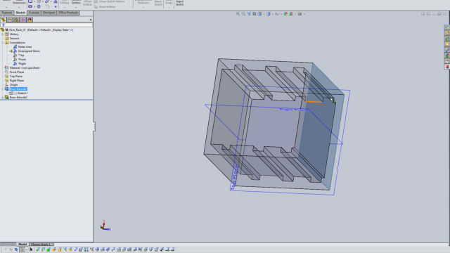
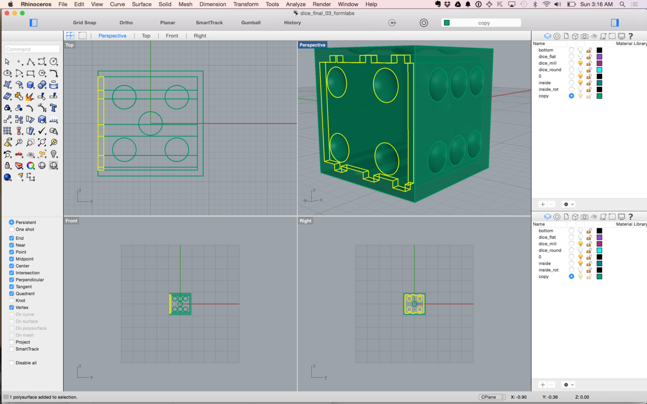
Since I didn’t want to mess with creating the perfect die model in SolidWorks, I exported the top view of the shelving as a dxf and imported it into Rhino. From that curve, created a model of the die with numbers and shelving as well as a front cover when all of the electronics are in,

This scale seems like a job for the FormLabs printer, since the z-axis (layers) are what largely dictate the amount of print time, I decide to print 4 and hope that a couple of them are successful.
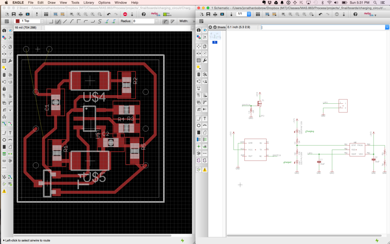
A charging circuit with a blue and green LED as status lights. The circuit is double sided and contains 6 pads for programming and charging the dice. The IC used to control charging of the LiPo battery is the MCP73831.
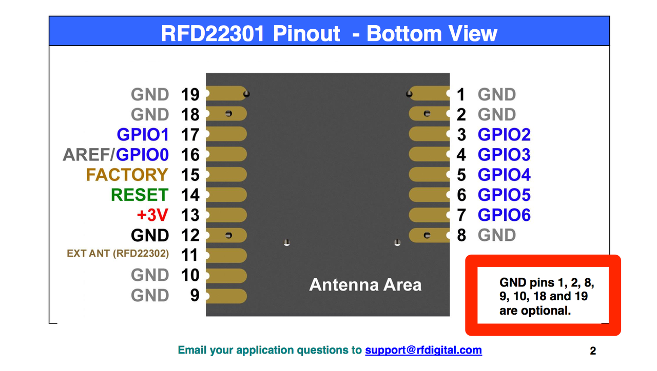
After vinyl cutting a circuit to connect all of the ground on the bottom of the RFduino, I read this. I decided to keep the grounded circuit there, but kind of sucks to find out it is completely unnecessary.
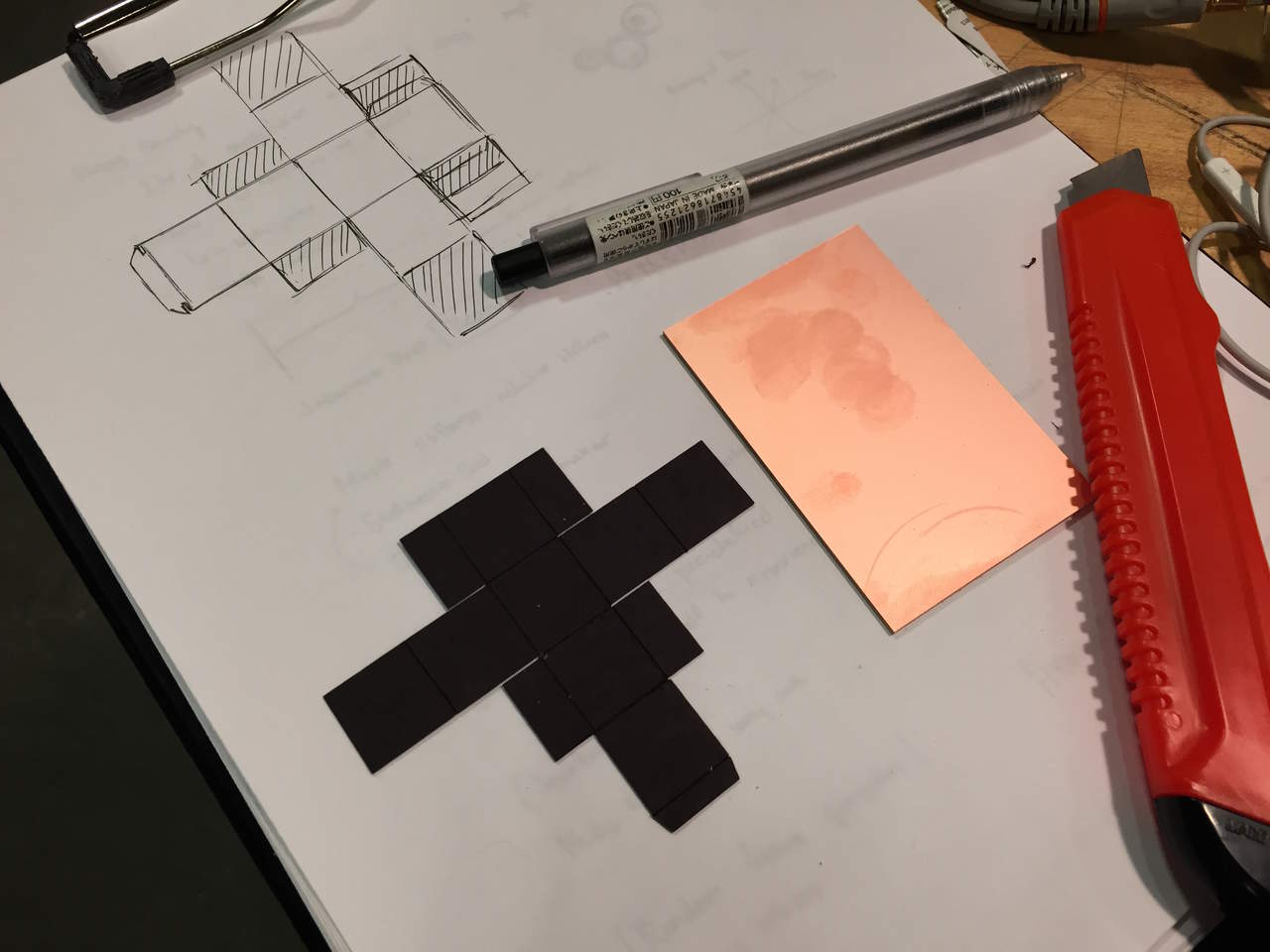
Quickest way to create a 16mm cube for prototyping, draw out a package design and laser cut it. The folding design requires no adhesives, simply press-fit.

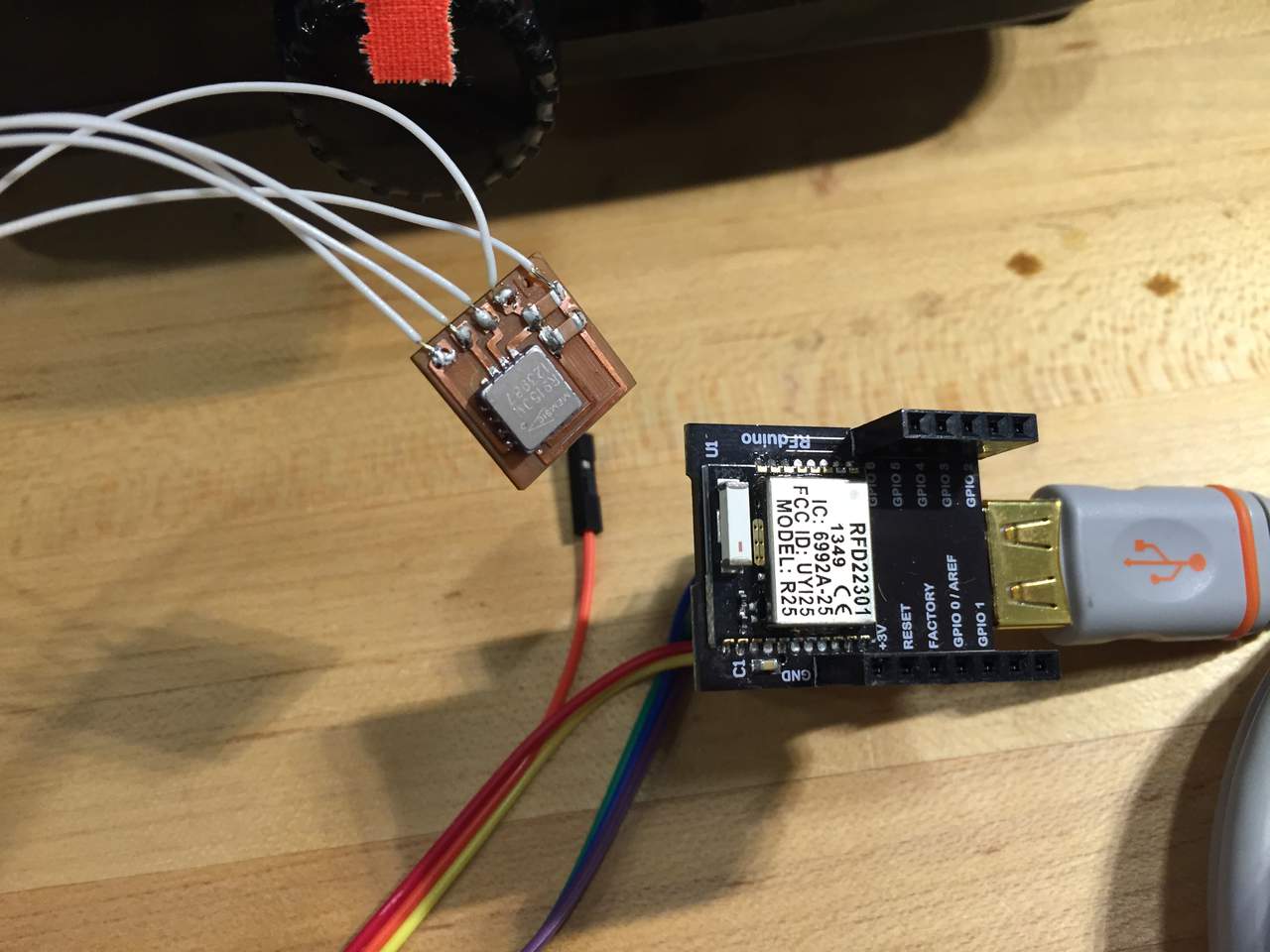
RFduino and 40mAh LiPo battery happy in their new temporary home.
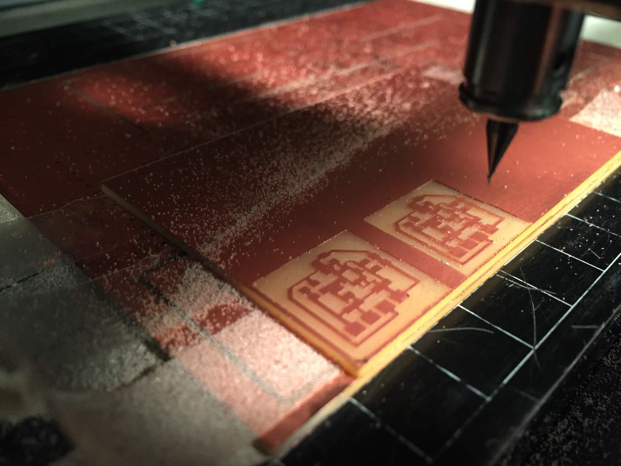
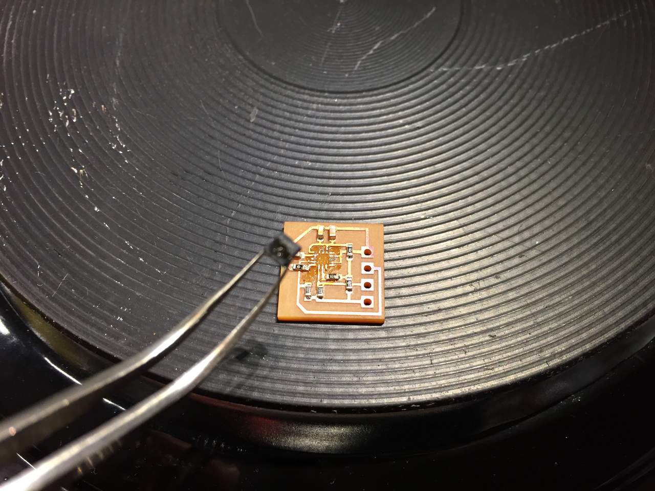
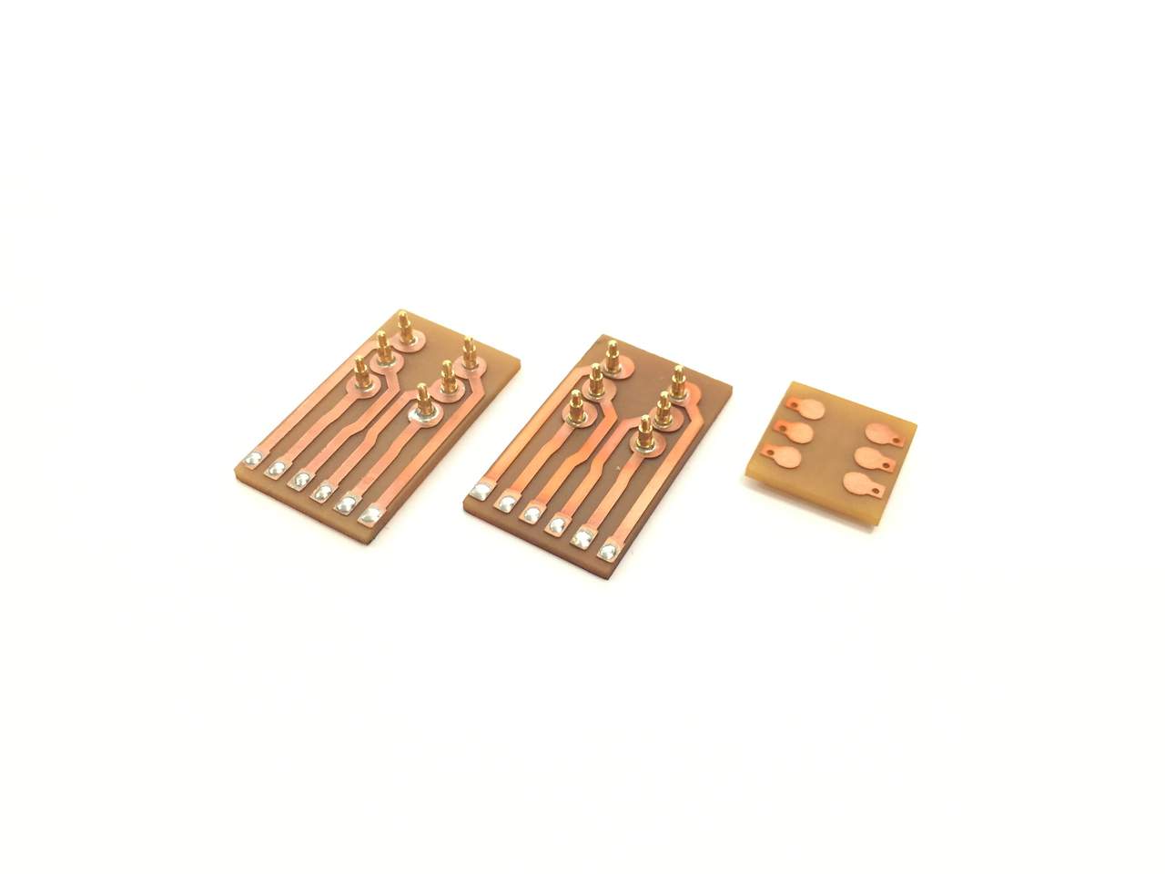
First pass at the 9-dof board with the 1/64th inch endmill. All of the resistors and capacitors will need to be 603 packages as opposed to the fab standard 1206 packages to fit on the board.
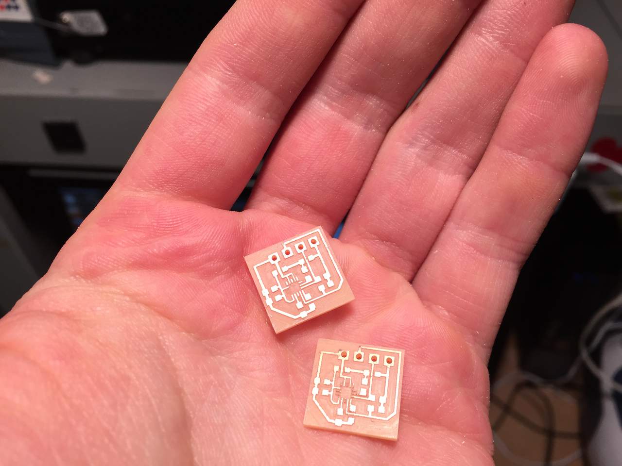
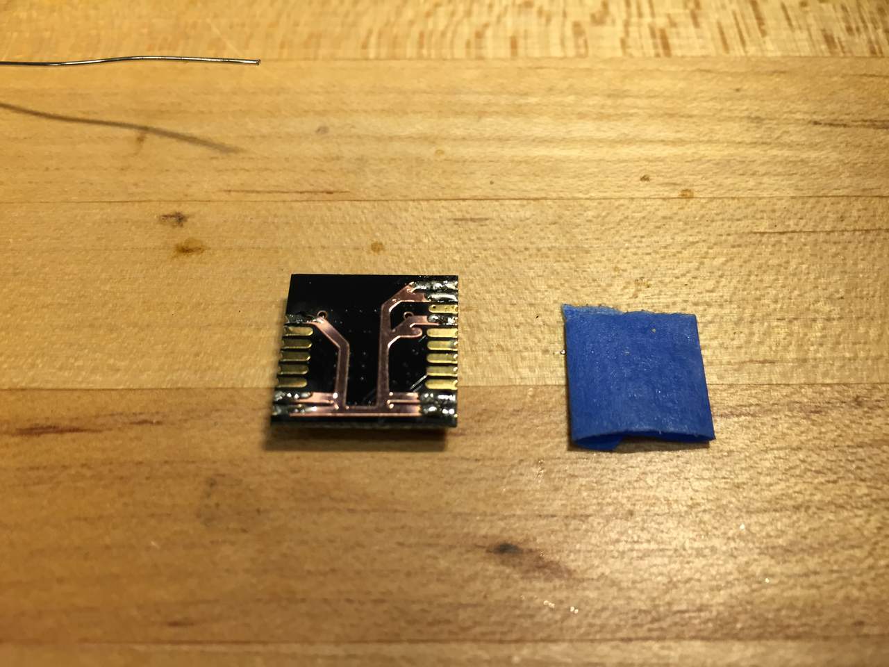
Finished milling 2 9-dof breakout boards using the 10 mil endmill on to get the smallest of details.
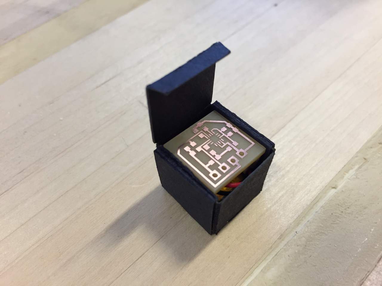
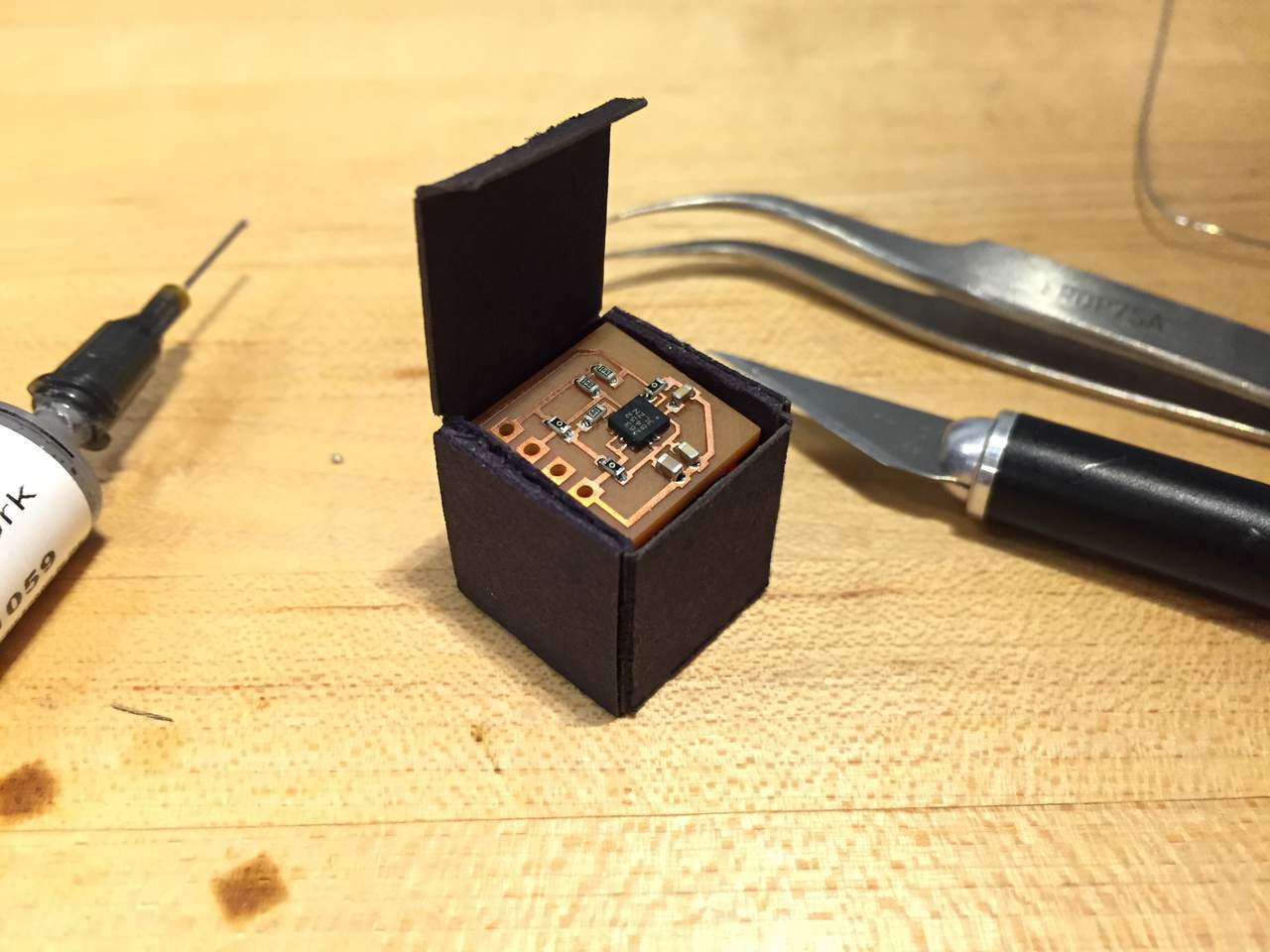
And sure enough, that board fits in its package, too!
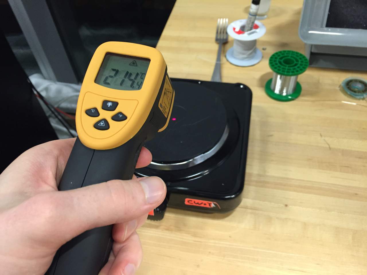
My favorite technique for soldering boards has become solder paste and a standard hot plate. To get the solder to flow nicely and not burn the board, I use an infrared thermometer to find when the plate remains at around 235º Celcius (270ºC tops) and then place my board with components on for approximately 30 seconds. It is obvious when they are done, since the solder turns bright silver.
All soldered on and back at home.
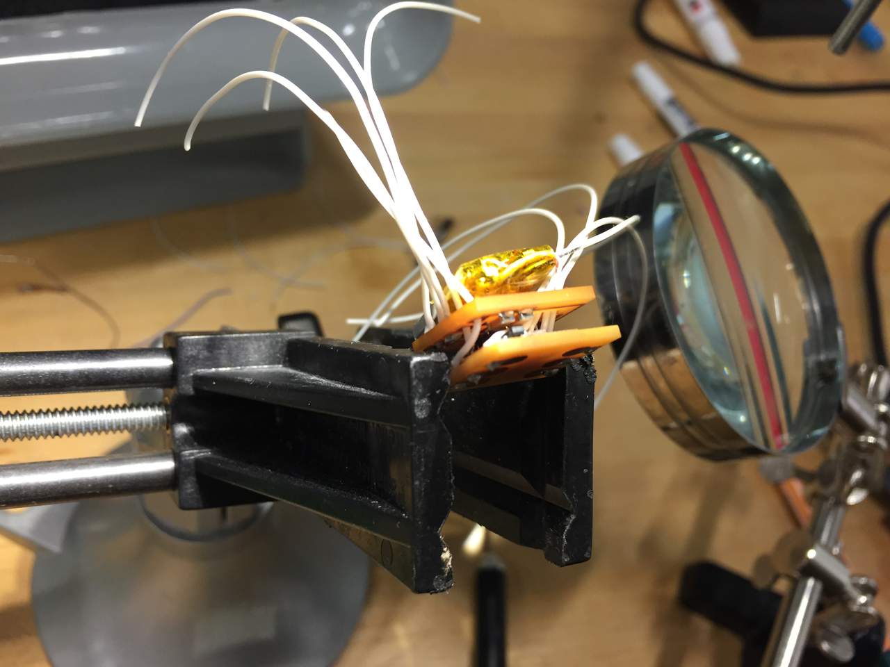
Hmmm, the I2C communication isn’t working, perhaps the chip is not seated properly. This started a long night of trying to place and replace this chip far too many times. Note, I am simply using the hot plate as a heat resistant surface for the hot air gun, and not heating up the hot place, since I don’t want all of the components heated up.
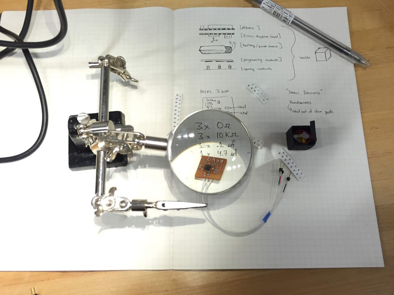
I actually don’t use the magnifying glass since I find it difficult to use, but I love the alligator clips for holding my wires in place.
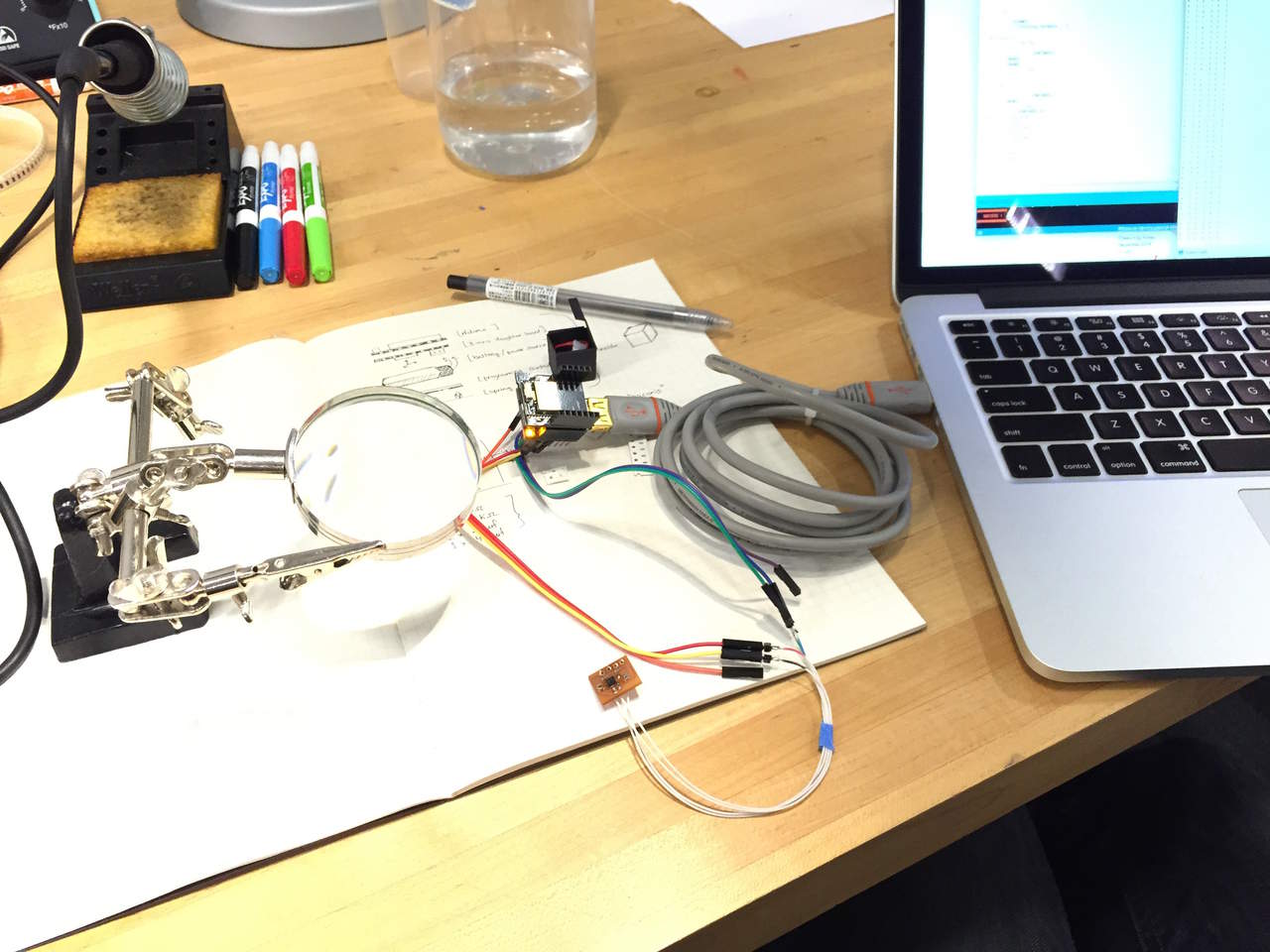
Testing out the I2C with a simple Arduino sketch that looks for the device and prints the results.
Testing out the analog accelerometer which worked the very first time I connected it. The readings are values around 512 that vary about 50 in either direction with a single G of force. This means that I will be able to get about 2 degree accuracy with the dice, which is plenty.
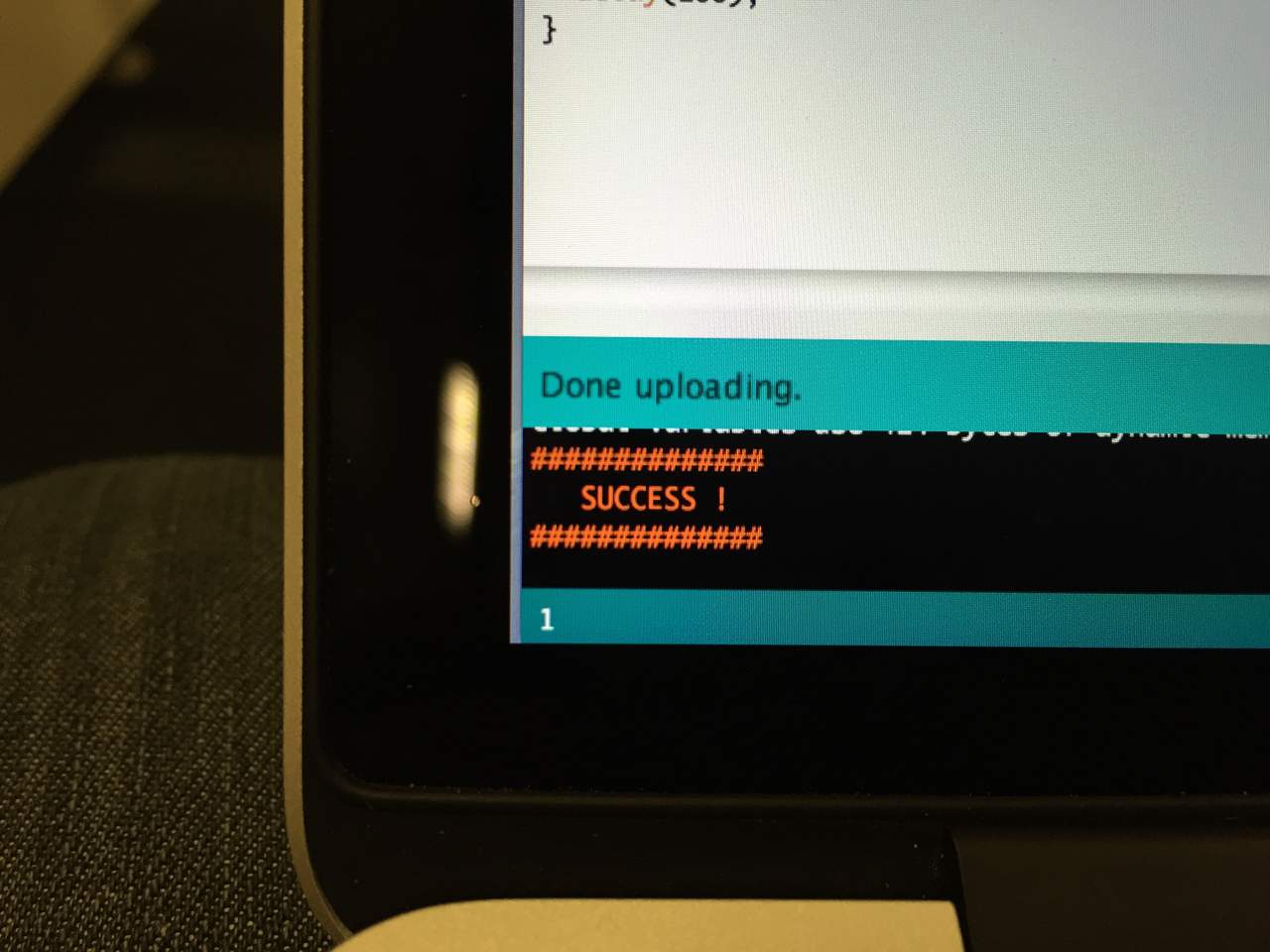
Success! Need I say more?

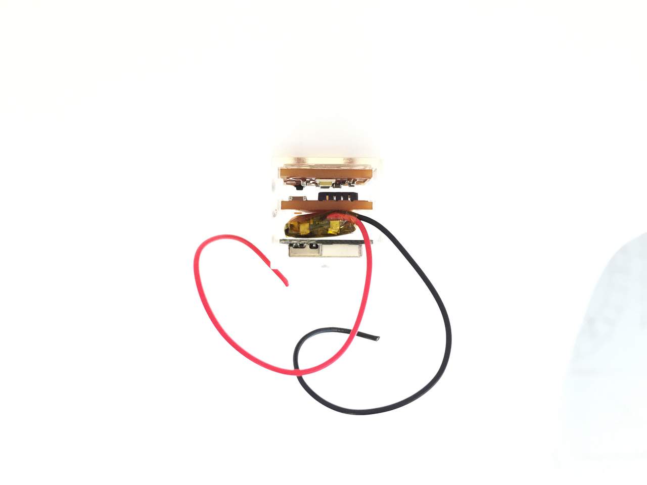
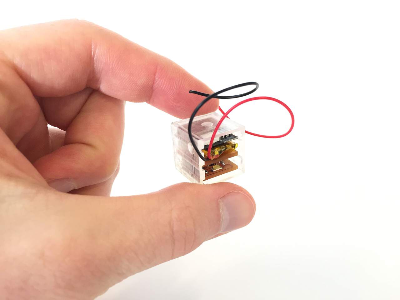
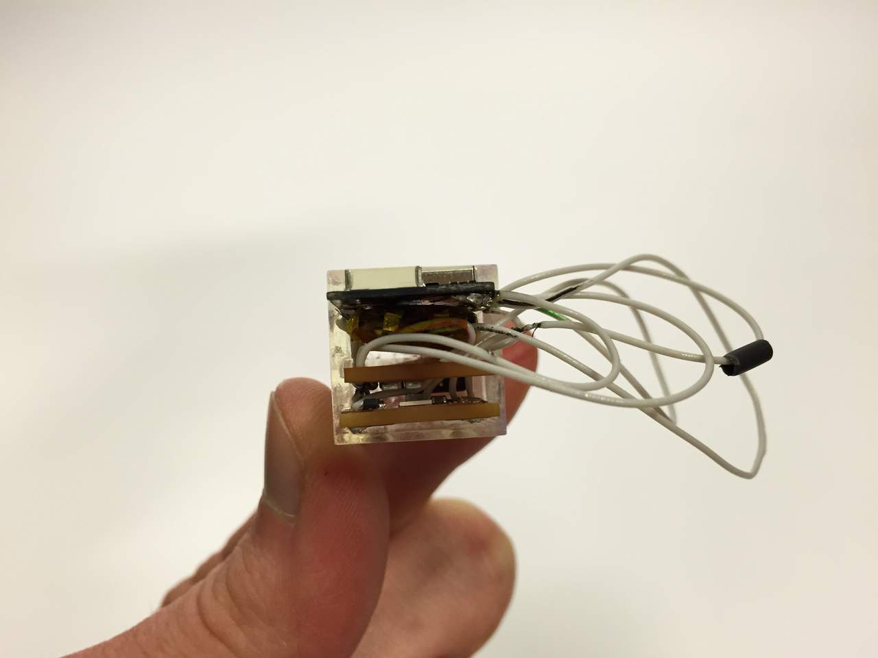
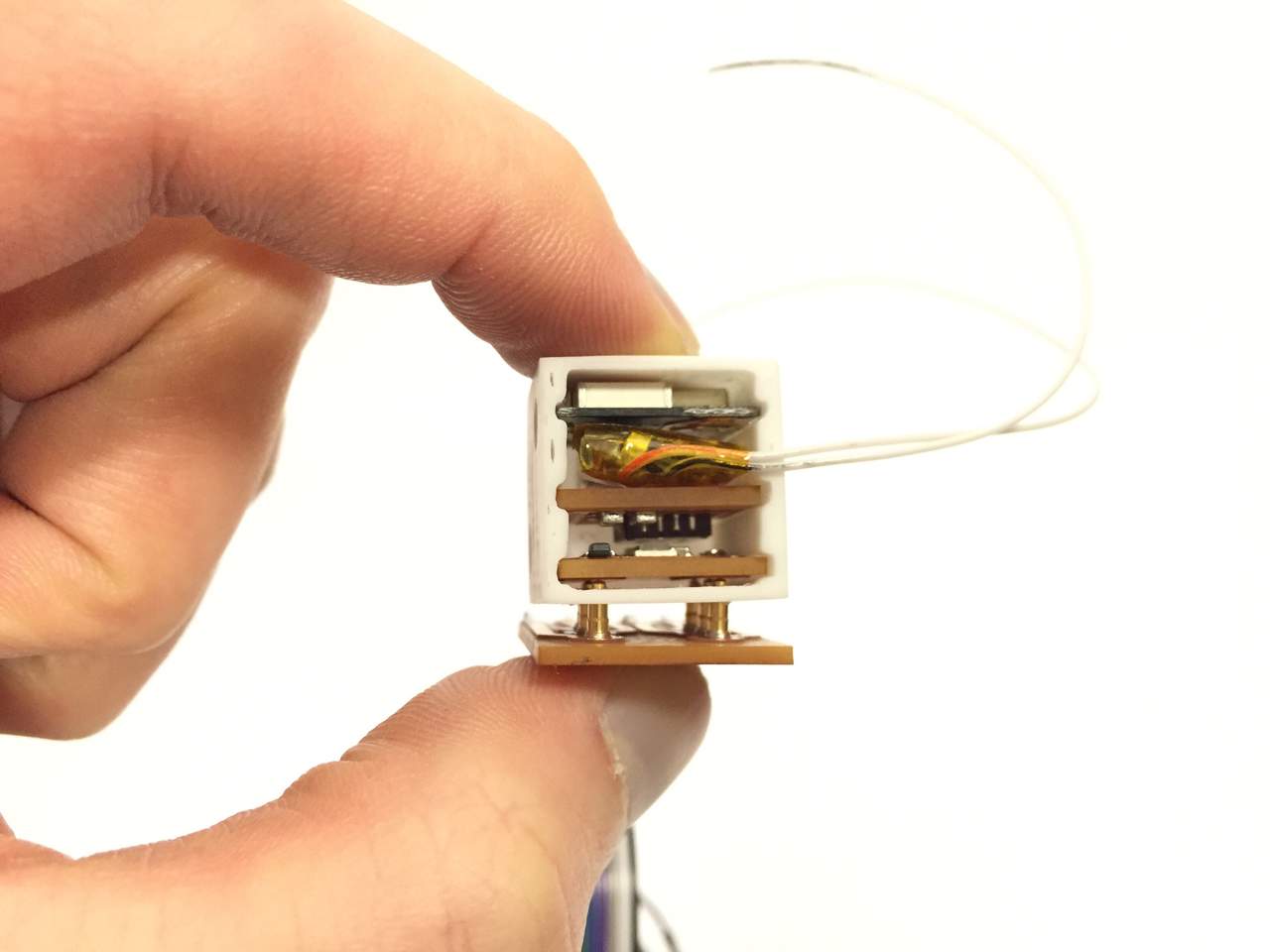
Starting to load final parts into their shelving unit.
Not counting wires, they all fit.
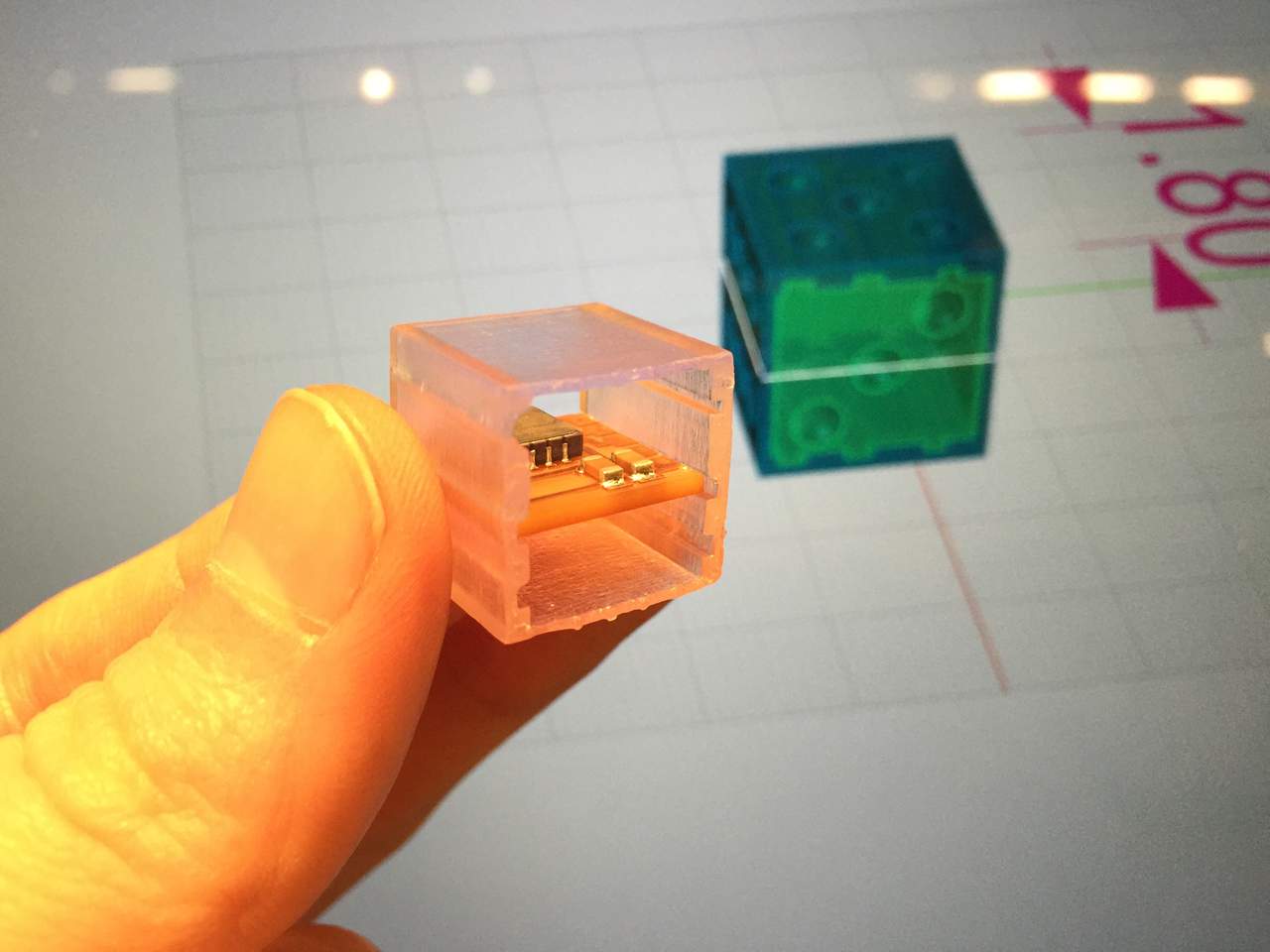
The clear FormLabs print came out with even more accuracy than the Makerbot, but support structure created some unwanted surface finish to the back side.

Using an ultraviolet light to finish curing the FormLabs resin. It seems that some of the parts come out a bit gooey even after washing them in IPA (isopropyl alcohol).
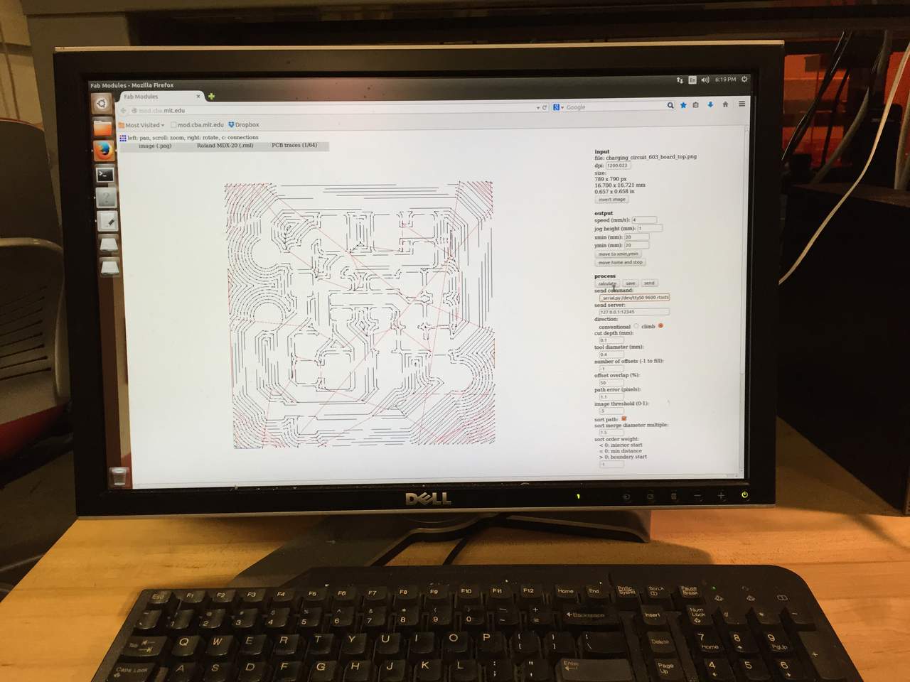
Using the fab module to mill my traces for the charging circuit.
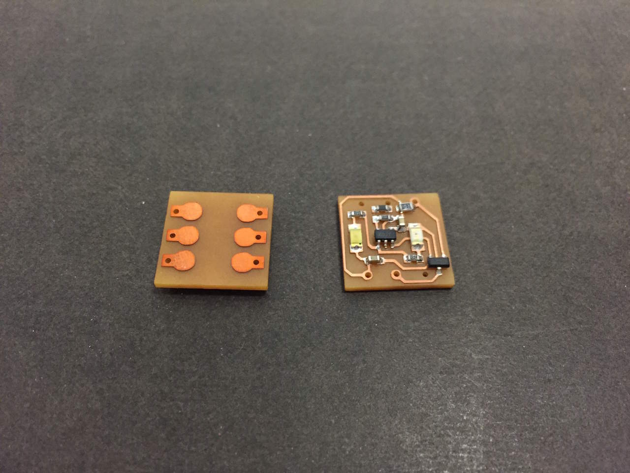
front and back sides of the charging circuit. My first 2 sided board.
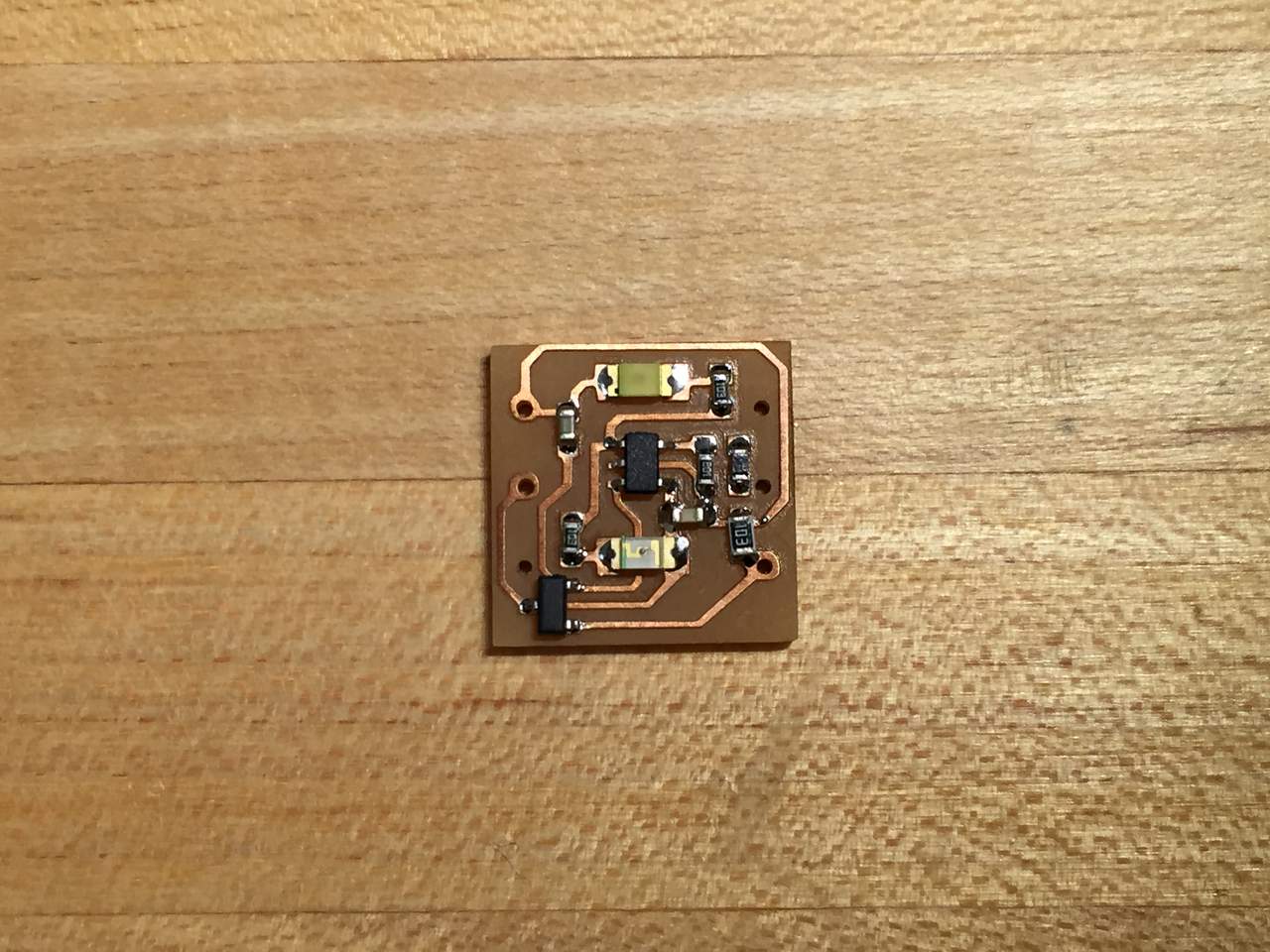
Solder paste creates quite nice connections.
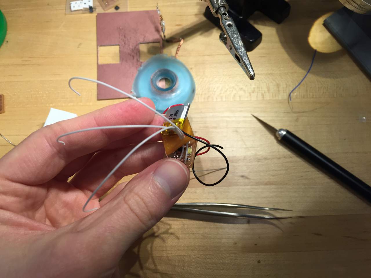
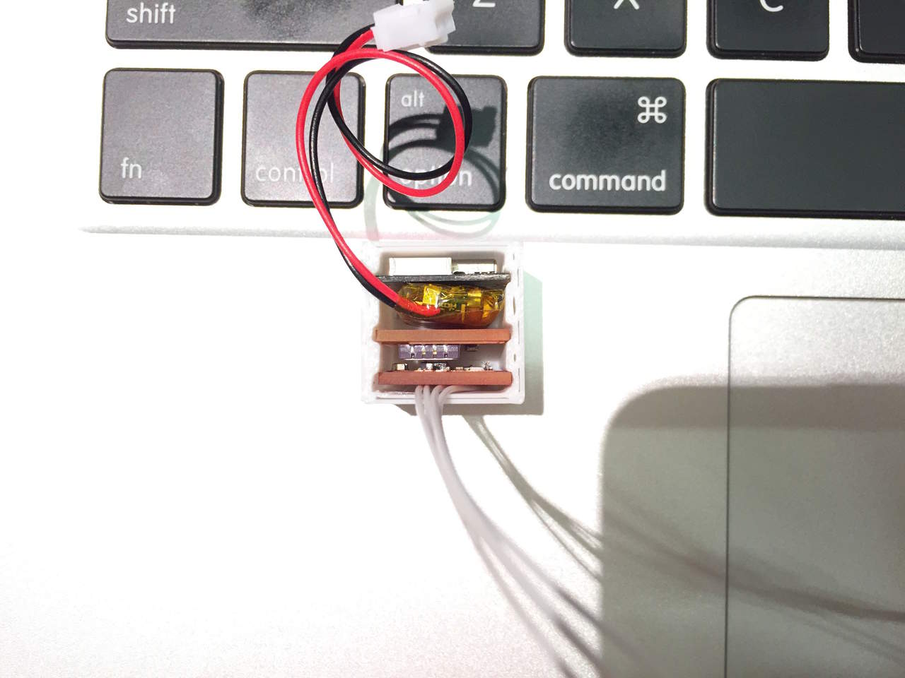
Starting to wire up the final dice by using the smallest stranded wire I had on hand.


C code for dice smoothing accelerometer data and calculating angle of rotation. Sending the calculated angle in a message for a connected BLE iPhone or Android device.
/*
This RFduino sketch demonstrates a Bluetooth Low Energy 4 connection
between an iPhone application and an RFduino.This sketch works with the the Dice++ iPhone application.
This sketch demonstrates publishing x, y, and z rotational values for
the dice, and the iPhone app will receive this information formatted in
a friendly constant length string to be parsed and inform the visualization.
*/#include
int x, y, z;
const int smoothVal = 30;
const int timeDelay = 10;const int timeDetermineRoll = 100; // 10th of a second
int xVals[smoothVal];
int yVals[smoothVal];
int zVals[smoothVal];int xSum, ySum, zSum;
int xAvg, yAvg, zAvg;
int prevX, prevY, prevZ;boolean newRoll = false;
String data;
double prevTime;
// Input pins for accelerometer data
const int xpin = 2; // x-axis of the accelerometer
const int ypin = 3; // y-axis
const int zpin = 4; // z-axis (only on 3-axis models)void setup() {
// this is the data we want to appear in the advertisement
// (if the deviceName and advertisementData are too long to fix into the 31 byte
// ble advertisement packet, then the advertisementData is truncated first down to
// a single byte, then it will truncate the deviceName)
RFduinoBLE.advertisementData = “dice++”;// start the BLE stack
RFduinoBLE.begin();Serial.begin(9600);
}void loop() {
x = getDegreeValueFrom8bitValue(analogRead(xpin));
y = getDegreeValueFrom8bitValue(analogRead(ypin));
z = getDegreeValueFrom8bitValue(analogRead(zpin));
// X
calculateXAvg();// Y
calculateYAvg();// Z
calculateZAvg();// TODO:
// Check values vs. previous values
// if changed values, then set to rolling
// if values stay constant for longer than the time to determine rool
// send a message that the value is determined, and set roll to true// Publish information over BLE after each specified amount of time
//wait .01 seconds (publishing ~100 messages per second!!)
if( millis() > prevTime + timeDelay) {prevTime = millis();
data = getStringWithXYZ(xAvg,yAvg,zAvg);
char charBuf[data.length()];
data.toCharArray(charBuf, data.length());int length = strlen(charBuf);
if( length <= 20){ RFduinoBLE.send(charBuf,length); }else{ RFduinoBLE.send(charBuf,20); // BLE packet is 20 bytes max. } Serial.println(charBuf); } } // void calculateXAvg() { // shift x values back in array for(int i=smoothVal-1; i>0; i–){
xVals[i] = xVals[i-1];
}
xVals[0] = x;// sum x values
xSum = 0;
for(int i=0; i<smoothVal; i++){ xSum += xVals[i]; } // calculate avg x xAvg = int(xSum / smoothVal); } // void calculateYAvg() { // shift y values back in array for(int i=smoothVal-1; i>0; i–){
yVals[i] = yVals[i-1];
}
yVals[0] = y;// sum y values
ySum = 0;
for(int i=0; i<smoothVal; i++){ ySum += yVals[i]; } // calculate avg y yAvg = int(ySum / smoothVal); } // void calculateZAvg() { // shift z values back in array for(int i=smoothVal-1; i>0; i–){
zVals[i] = zVals[i-1];
}
zVals[0] = z;// sum z values
zSum = 0;
for(int i=0; i<smoothVal; i++){
zSum += zVals[i];
}// calculate avg z
zAvg =int(zSum / smoothVal);
}// return a value between 0 and 180 from voltage levels
int getDegreeValueFrom8bitValue(int val)
{
int degree;degree = int(90 * (val – 520) / 50.0); // approx 512
// clamp value between -90 and 90
if(degree < -90) degree = -90; else if(degree > 90)
degree = 90;degree += 90; // put in the range of 0-180 :)
return degree;
}// create a string from int values for rotation
String getStringWithXYZ(int x, int y, int z)
{
String str;str = “x”;
str+=getThreeDigitString(x);
str+=”y”;
str+=getThreeDigitString(y);
str+=”z”;
str+= getThreeDigitString(z);
str+=”/”; // this last character gets lost in transmissionreturn str;
}// create a string from an integer to take up 3 characters of space
// this is inefficient, but keeps formatting nice
String getThreeDigitString(int val) {String str;
if(val < 10) {
str = “00”;
str += val;
}
else if(val < 100) {
str = “0”;
str += val;
}
else {
str = “”; // needs to add the integer like so, otherwise it complains about the type
str += val;
}return str;
}void RFduinoBLE_onDisconnect()
{
}