Input Devices
This week, I played around with Geiger counters that I borrowed from the physics department with the hope of building a cosmic muon detector (spoiler alert: hitting a few errors that prevented me from getting this project up and running).
The Earth is constantly being bombarded by high energy radiation originating from explosions outside our Solar system. The radiation itself is primarily composed of protons, but the protons will interact with particles in our atmosphere causing showers of secondary particles. Muons are the most energetic of these particles and will penetrate the atmosphere, often reaching the surface. We can detect this radiation using Geiger Tubes, basically a tube filled with gas that is ionized by incoming high energy particles.
- Project:Sensor Input
- Date: November, 2014
- Skills: Circuit debugging


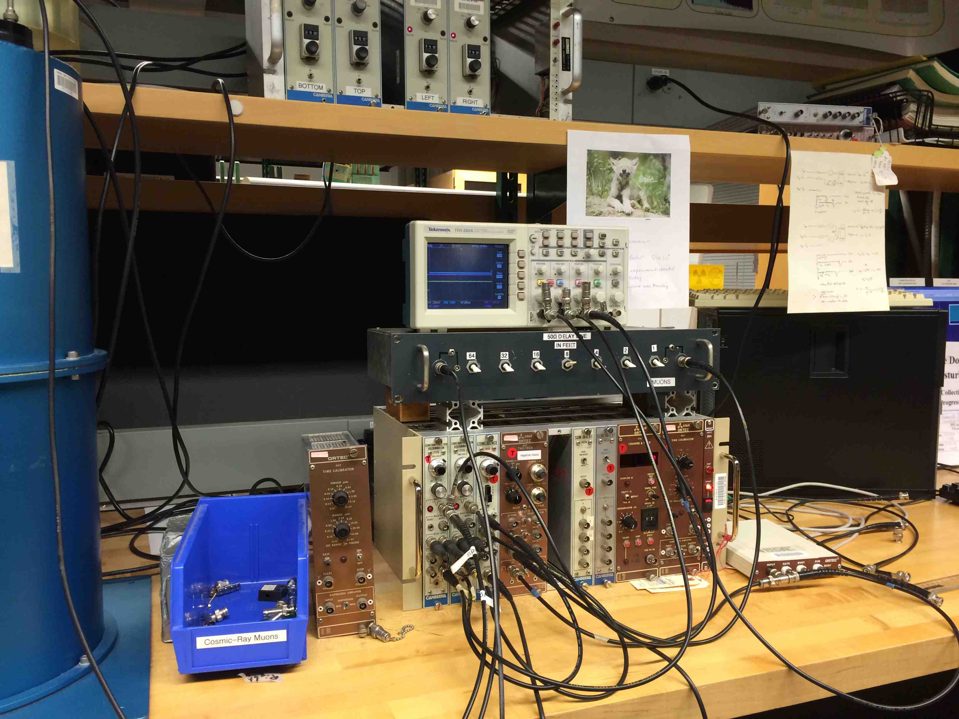
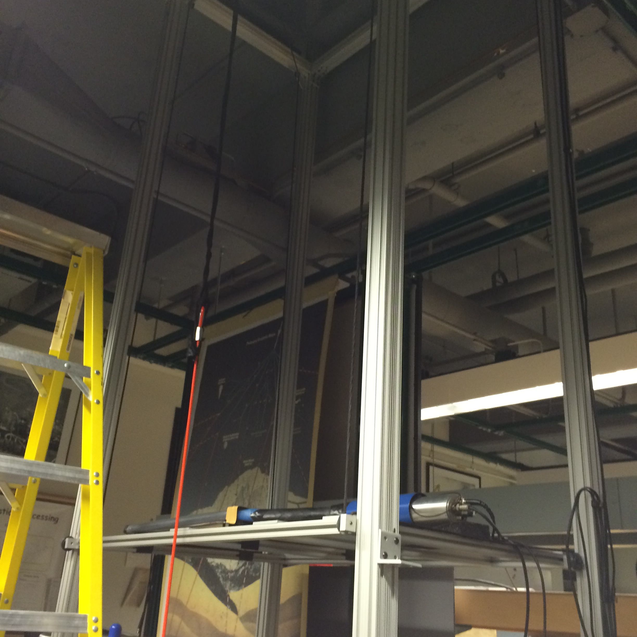
I began by borrowing geiger muller tubes from the undergraduate physics teaching lab. They have a pretty sweet cosmic muon experiment of their own (made using scintillation material and photomultiplier tubes
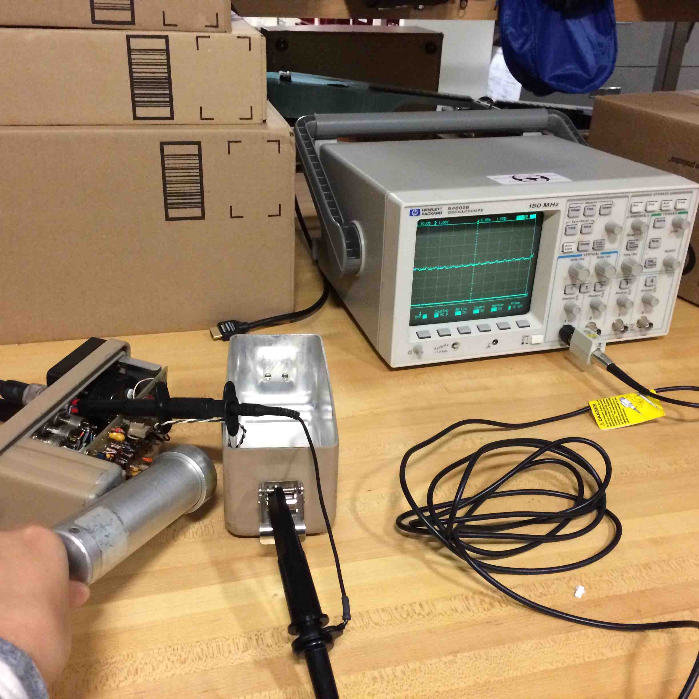
Next, I began testing the geiger tubes. There are some pretty sweet electronics inside. By reading blogs from hackers who have undertaken similar projects, I had a rough sense of the requirements for making these tubes operate appropriately: the gas needs to be suspended at a really high voltage (~500 volts) and small fluctuations on the order of a few volts represent signal (when gas ionizes, a small current is created). Through my testing, I discovered that the current output of the tubes was so small that even my 100x scope probe was drawing too much current! As a result, I only saw signal when doing some funny things with choosing my ground. Not sure why this changed things.
You can view a video of the original signal I saw on the right. Note that the tube is most definitely at 500 volts, so there are definitely some fishy things with how I was detecting this signal. Whenever I did read off 500 volts from the geiger output, I wouldn't see any signal due to the scope probe drawing all the current.
Next, I examined some circuits other people have designed, and also spoke with some electronics gurus including Jeff Duval about how to design my circuit. It would require a high voltage power supply (which I could build using a transistor) I was also considering getting my hands on a high voltage supply that plugs into the wall, but these can be pretty dangerous as there is risk of high current running through you (note: pro tip I heard from multiple people is to keep one hand in your pocket while working with high voltage supplies).
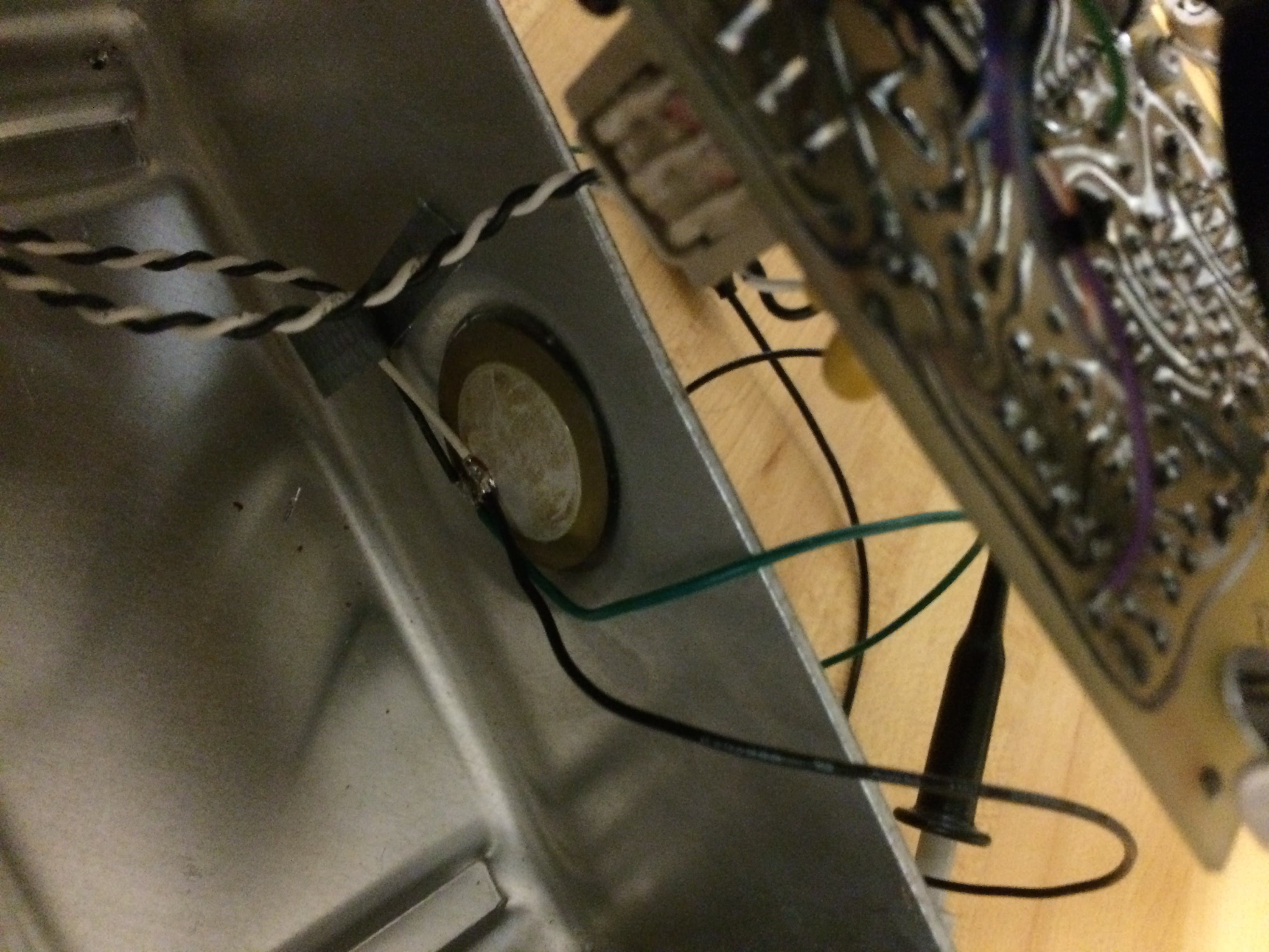
There is then some massaging of the output signal in order to get it read in as a digital high...in the end I got nervous about this approach as my first prototype, and instead changed course and decided to take signal from the audio output of the geiger counter (there's a piezo speaker that outputs small bursts of current).
I soldered wire to the piezo speaker and saw that there are bursts of ~800mv-1v pulses every time the geiger tube detects something. This seemed like a reasonable signal to pick up for my first prototype.
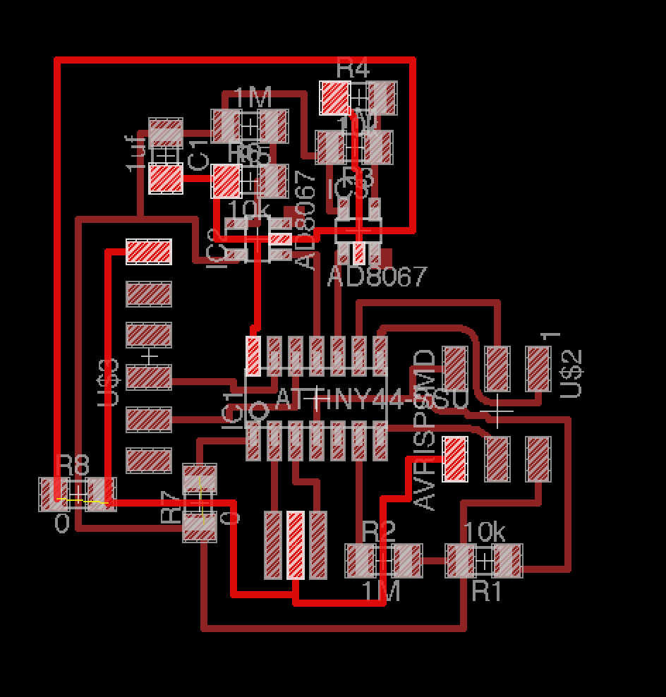
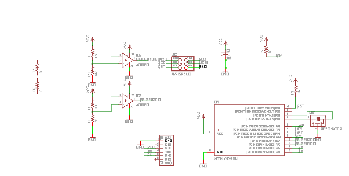
Now it was finally time to go off and design my circuit board. Because my signal was <1v, I knew I had to boost the voltage to 5V in order for the signal to be registered as logic high. Although the ATTiny44 has an on-chip ADC, I went with discrete comparators because: 1. It's educational for me 2.I was a little hesitant about how to actually use the on-chip ADC (additional code needed?) and 3. I needed two comparators and my understanding was that there is only one on the chip.
I asked about using a discrete AND gate as well to test performance of software vs. hardware ANDs, but got feedback from Neil that this can just be looked up on the data sheet and software should be fine even if you need a very fast trigger rate. (NOTE: I needed an AND gate because my goal is to detect simultaneous signals in two stacked geiger tubes).
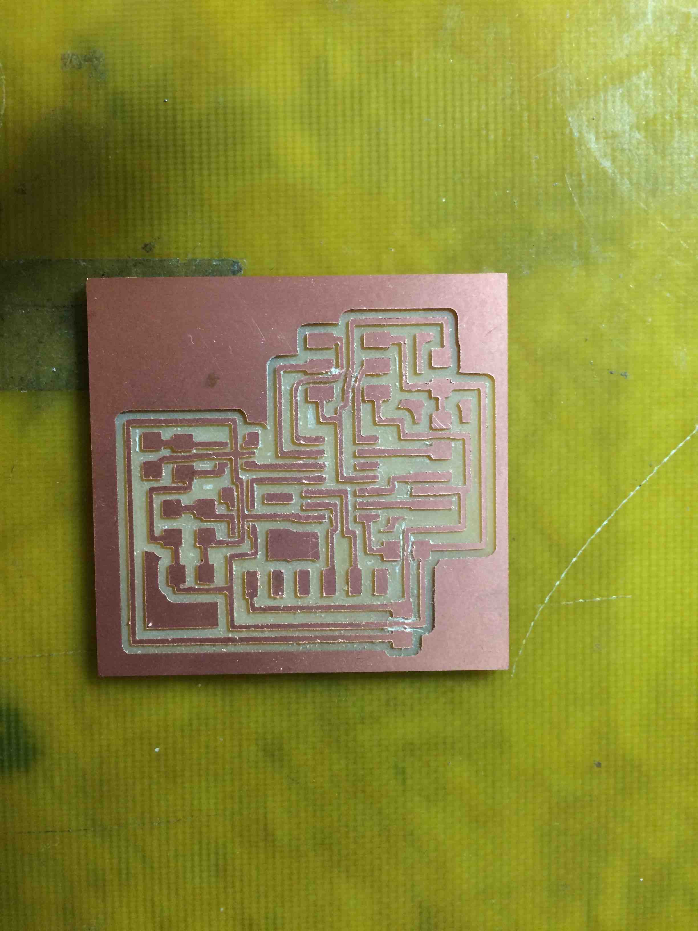
Finally I felt comfortable with my circuit layout, and then it took me a WHOPPING 6 HOURS to route. Why so long? I don't really know :( Guess I'm still getting the hang of things. It was very frustrating. At one point I found a solution, but subsequently discovered that some of the conncetions in my schematic hadn't registered in the board due to a labeling issue. Double check your labeling!
I added pads to attach my speaker wires, and I forgot to add pads for speaker ground but it shouldn't be a big deal.
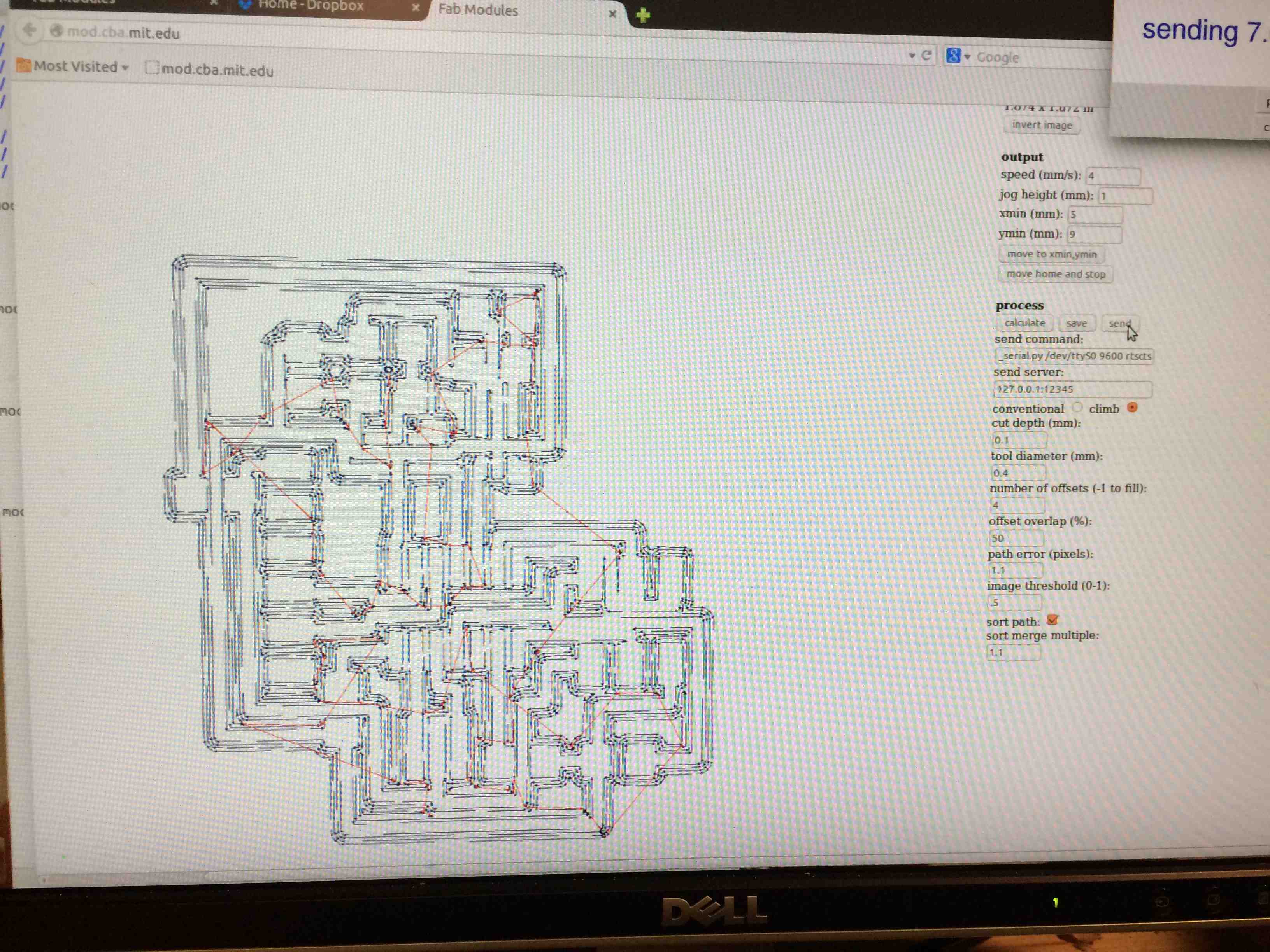
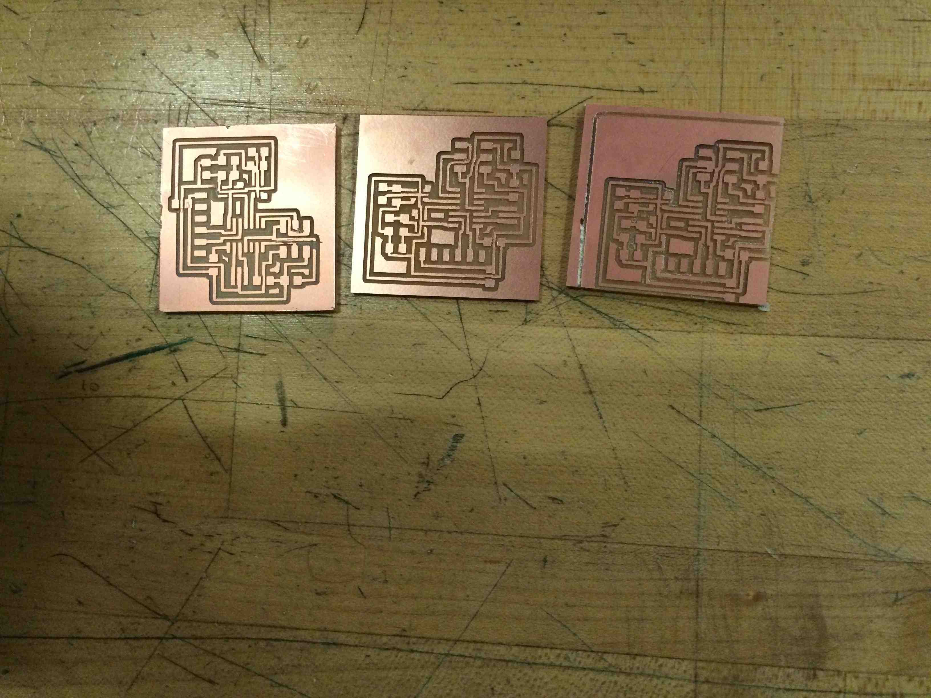
Next came printing (finally! After a whole day of circuit board routing!) It took me 3 attempts. MAKE SURE your double stick tape is strong, and make sure that you leave enough space between wires for a 1/64 drill bit! Even after attempt 3, I had to go in with an Xacto knife and repair some connected traces.
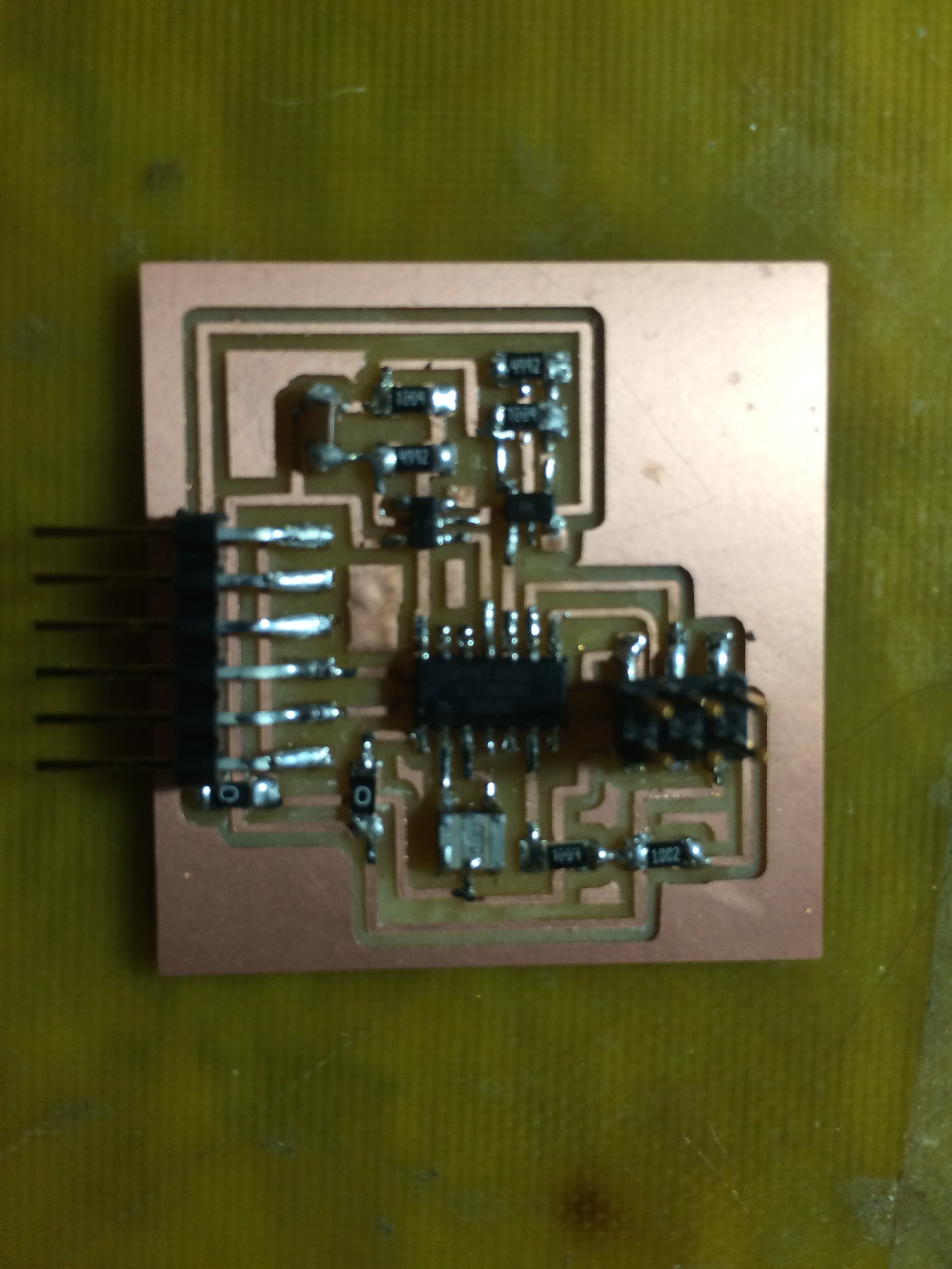
Next I stuffed the board, which went pretty smoothly.
While programming, I got an error: "warning: Sampling of the RDY/nBSY pin timed out
avrdude: stk500v2_paged_write: write command failed" Some helpful folks in my lab helped to debug, and we determined that my VCC pin on my input device isn't connected! (you can see this on my board). The board had appeared to work because internal protection diodes were supplying some power. I dumped some solder on the board to connect my VCC pin to a power trace and now things programmed smoothly.
I used the Arduino environment for programming, and now, sad things happened. First, I got Software Serial up and running, and it read roughly 909 consistently when I output the value of the geiger port, regardless of what I did with my signal.
Also, I used the probe to measure the signal entering and leaving my comparator, and in both cases it still appeared to be roughly one volt pulses, causing concern as to whether the comparator is doing what it's supposed to. This is where I've left off for now...perhaps I'll have it all up and running by next week! (With an output vibrating glove so you can feel the muons??)
Here is a video of my comparator woes: first I show the output signal of the geiger into the comparator, and then I show the output of the comparator.
My SUSPICION is that I've not been careful enough with ground, and with making sure that the ground of the geiger is the same as the ground of the chip.
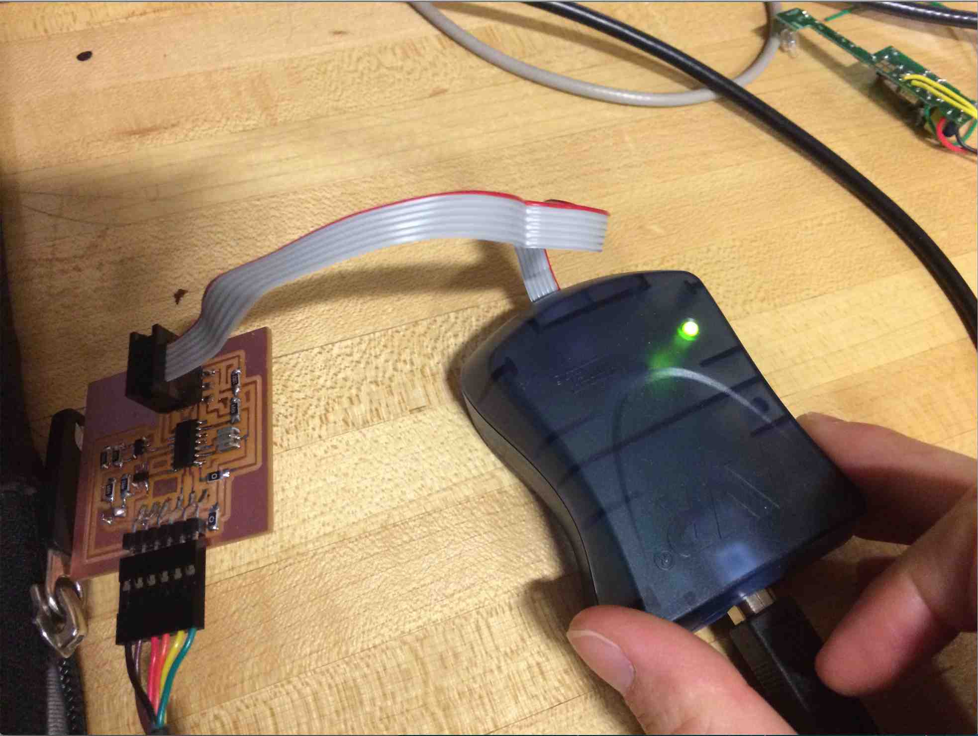
UPDATE: I concluded this week's project by getting some flavor of signal up and running. I did this by switching to analog input bypassing the comparators on my circuit (e.g. I connected the output of the piezo speaker of the geiger counter directly to the input ports of my chip). In the video below you can hear that the beeps of the geiger counter are picked up by my program as hits.