Juliana Cherston

How To Make Almost Anything

Networking and Coding

This week I decided to make my vibrating glove operate via Bluetooth. For my final project, I still intend to use this glove to allow users to feel cosmic radiation. However, I also see this as a platform with more practical uses. For example, imagine you are biking in a city that you know reasonably well. You're going to a new place and could just use a few simple cues when you need to turn. What if your pinky and thumb vibrations 
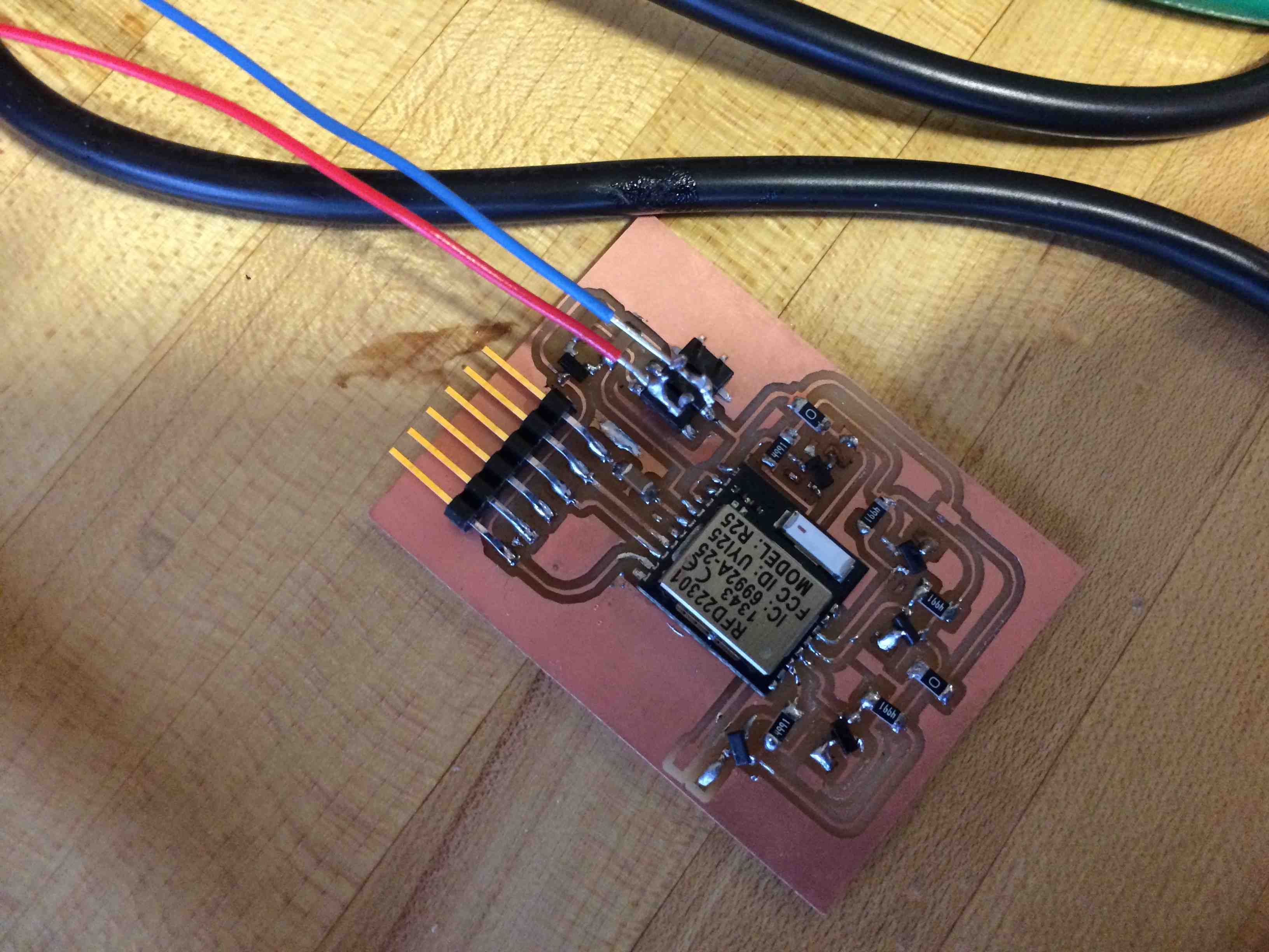
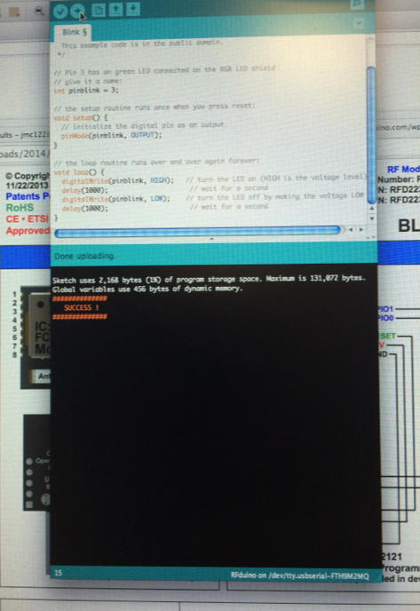
could indicate it's time to make a left/right turn? In order to build this, I ultimately made use of an RFduino, a chip that is compatible with both iPhone and the Arduino programming environment. This will (in the future) allow me to build an iPhone app that sends simple "buzz" signals to my glove when I'm approaching a turn.
  • Project:Networking and Coding
  • Date: November, 2014
  • Skills: Voltage Regulator, MOSFETs,RFduino/Bluetooth, iOS
I started off by improving on my board design from output week. I substituted my voltage dividers from last week with a single voltage regulator (RFduinos run on 3.3 volts). I also added MOSFETs to drive my vibrating motors. I removed the 3x2 pins since I would not be using the AVRISP (RFduino is an ARM device, and anyway fuses and such are already set so I only need to program my code, which I can do via FTDI cable). Most websites recommend getting your hands on a USB programmer shield for the RFduino, but I found that connecting ground, reset, RX, and TX to USB via FTDI worked just fine.

NOTE: I made two critical errors in the above design. Firstly, I flipped source and drain on my MOSFETS above (didn't pay attention to the direction of the internal diode in the diagram above). Second: I accidentally flipped TX and RX from what the RFduino expects. Correct connections can be found in this forum thread: http://forum.rfduino.com/index.php?topic=75.0. In order to remedy this, I cut the TX/RX traces and soldered jumper wires. I soldered on the MOSFETS upside down and sideways (thanks for the hacker tip JF!) This of course caused my board to be a little messy, and I'm eager to mill a cleaner version.
Next I followed the instructions on RFduino to set up my programming environment. This involves installing a plugin for the Arduino programming environment so that RFduinos will be recognized, and it also involves downloading the appropriate FTDI driver. The RFduino site provides good instructions. Soldering the RFduino was nontrivial, and I realized in my initial solder attempt that RX and TX were connected under the board. I tried to remedy this by reflowing with a heat gun. It worked for a little while, but ultimately the problem re-emerged, and programming stopped working. This forced me to remove and re-solder the chip. The problem was obvious when removing the chip (see pic below). If you hit errors when trying to program your RFduino, Make sure that: 1. Your power supply is on 2. RX and TX are connected to the right FTDI pins.
Some more info about RFduino: RFduino consists of a very small Arduino compatible ARM Cortex M0 microcontroller that is enabled with Bluetooth Low Energy. Bluetooth Low Energy (http://en.wikipedia.org/wiki/Bluetooth_low_energy) is designed to significantly reduce power consumption of Bluetooth-enabled objects. It operates on the 2.4GHz-2.4835 GHz ISM band (same as classic Bluetooth) but uses different channels. As with traditional Bluetooth communication, data is transmitted using Gaussian frequency shift modulation. This is a modulation scheme that uses a filter to smooth deviations from a particular frequency, but is otherwise based on frequency shift keying technology. In this scheme, changes in the frequency of a carrier wave are used to encode 0's and 1's.
In addition to reducing power consumtion, BLE-enabled chips can also communicate more easily with iOS and Android devices (This is a big deal: before BLE, Apple required users of Bluetooth to subscribe to their MFI program (https://developer.apple.com/programs/mfi/) or jailbreak the device).
I used the very simple blink for RFduino code to control my motor. RFduino also supplies sample iPhone apps, and with a lot of patience I ultimately got a button on my iphone controlling one of the motors. I've downloaded the sample Bluetooth application on XCode and the next step is to study the code and modify it to be able to send different pieces of data via Bluetooth to control different motors. I also want to rebuild my board so that it is cleaner (after all this hacking!) For now, I'm very happy to have gotten Bluetooth communication between my iPhone and my board up and running!

Here is a screenshot of the sample iPhone app UI detecting an RFduino when I feed power to my RFduino (NOTE: the code to list all detected RFDuinos was part of the RFduino sample application. I did not write it)

Now that I had a basic app working, I continued working on my cycling app. First, I modified the code so that it could talk to any motor on the device. I wasted a lot of time writing my own functions until I realized that the sendByte function took an integer that I could then read within my Arduino environment. So that was easy enough. I then delved into the dubious world of iPhone maps. Specifically, I decided to use the built in MKMaps I found that it's extremely easy to use the tools for certain class, and found that it's extremely easy to enable certain functions (such as embedding a map in an app with the user's current location indicated) but a lot harder to do somethings that have perhaps been intentionally obfuscated (such as finding the GPS coordinates at which each route.step.polyline begins at. I also began to play with iOS GPS location manager, which makes it fairly easy to keep track of a user's location at a frequency and to a degree of accuracy that you specify. Some things I still need to think about are: what additional steps should I take to ensure that the app's constant pulling of location doesn't drain the battery? Is it in fact possible to retrieve GPS coordinates of each step from the route.step property? (I may be able to project both the user's current GPS location and the route.step initial point onto a MapView and compare these values, but it seems hacky and I couldn't find anyone else who had done it this way. So, for now, I just used some test direction data as well as the user's current location in order to get this up and running :) Next step is subbing in real direction data! You can view my ViewDidLoad function by clicking here.