Kate Mytty

How to Make (Almost) Anything

Project 10: Input Devices

I set out to make a phototransistor to sense the status of light. This will ideally fit into my final project as I’d like to be able to sense the status of light and use that to switch on other lights and perhaps use that as the means to tell a motor to turn what will end up being a mobile (think Alexander Calder with lights!).

  • Project 10: Input Devices
  • What: Make a PCB Board with a Phototransistor

Project 10a Project 10b Project 10c
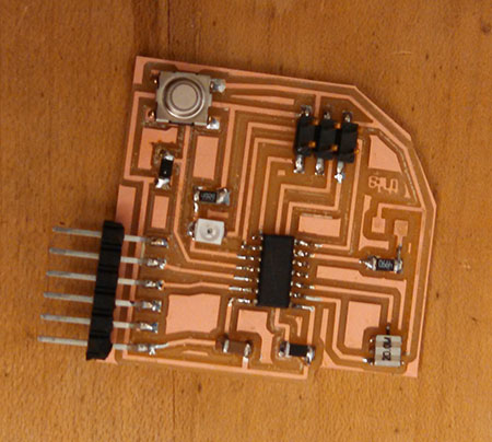
Step 1: Make the Board.

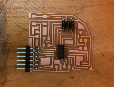
The first step was to make the board, mill the board, stuff
the board and test with voltage meter. as I mentioned
in previous electronic efforts, Prashant who TAed our earlier electronic sessions suggested milling only the three major components first — the micro controller, the FTDI header and the 2 x 3 header. As I stuffed the board, I tested each step with sample code.

Project 10dProject 10e
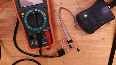
Step 2: Test board with voltage meter and stuff the remaining board.
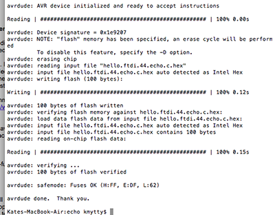
The results turned out fine - which meant I
was ready for a final round of programming.
Project 10f Project 10g
Step 3. Program the Board.
This took some time to get right. Honestly, I looked at the
original code and had no idea how to adapt it
for an ATTINY44 and adapt to my board design. It
took quite awhile to install the Python program that could
launch the python test. To save other folks some
time, when using a ATTINY44 with a similar board design, here’s how I adapted Neil's code for my board design:
The make file:
The c code to be compiled on the board:

I had to replace the phototransistor and microcontroller once or twice;
TA Will said that 1 in 10 ATTNY44's have clocks that don't
time properly -- which seem to be causing
trouble. Then the phototransistor was faced in the
wrong direction. You can see that it finally worked
after lots of experiements.

2014 Kate Mytty. This is under Creative Commons. Please do let me know if you use something.

Powered by Type & Grids