Kate Mytty

How to Make (Almost) Anything

Project 15: Final Project

what does it do? My goal for the final project is to create a light in the room that will turn on when the lights go off — a night light. It would be connected to my computer and turn on as the light goes down

who's done what beforehand? Lots of people have made lights or some version of lights. My original thought was do a design that felt similar to this birdhouse: http://scoutmob.com/p/The-Right-DIY-Birdhouse-Kit.

what did you design? I designed an interlocking set of pieces made from simple wood that I found at Dick Blick Art Supplies. I also designed a board with lights that would turn on as the light in the room went off. Originally, I had a circuit board and tried two different iterations -- along with a few other designs of board. After none worked as expected, I ended up using an Arduino to get the light effect.

what materials and components were used? For the original board, the materials are listed below. The LED strip was a flexible light strip that was a warm white color from SuperBright LEDs for $9.95.

For the physical design, I originally used frosted acrylic 24 x 48” Acryllic Satin Ice Sheet from US Plastic for $61/sheet; after the acryllic didn't work after the original laser cut, I moved to using wood, which I found was a healthier material and I appreciated the naturalness of the material. It was $2 per 12 x 12" sheet at Dick Blick art supplies. I used about 10 sheets to prototype with - or $20.

what parts and systems were made and what processes were used? Three parts were made:
1. The wood shell for holding the light, laser cut
2. Circuit board; made using the modela
3. When the first circuit didn't work, a circuit board using an arduino

What questions were answered? To make an interlocking box that holds together by itself takes a little experimentation to get the right kerf that allows for the material give and the laser. I found that right fit was a kerf (or overlap) of 0.0025".

The design has to fit the electronics. This is the first individual project where the electronics had to fit snuggly in the box. To that end, I made a few tabs that would allow walls that held the arduino board in place. The original design for the circuit board was to have the circuit board snap into place.

In the process of testing the circuit board, I finally remember the polarity of LEDs and phototransistors (yes, I’m still a beginner!)

How was it evaluated and what are the implications? I was evaluating based on whether the light would turn on or off in light and the size used that would fit on my desk. Both worked, when using the arduino.

For the design of the light fixture: It turned out as I expected. I'd add a bit of glue in the final rendition. I enjoy the design and it achieves what it needs to in terms of size and letting out light.

For the electronics: I spent a ton of time on this - electronics are still not my strong point. I attempted the usual ways of starting simple and testing the microcontroller and then adding piece after piece. I tried this on three boards. It was frustrating to make multiple boards and still not be able to get anything working. I worked with a lot of people to test out the design, the parts and pieces and the code with no luck. The arduino worked and while it is not a homemade circuit board, it does the trick.

Implications?
Right now I'm using an Arduino, which works well for me as it allows me to reconfigure the design. If I were to design a circuit board again, I'd work to start simple -- with just making lights light up and then move to a phototransistor over time.

  • Project 15: Final Project
  • What: Light in the corner

Project 15b Project 15c

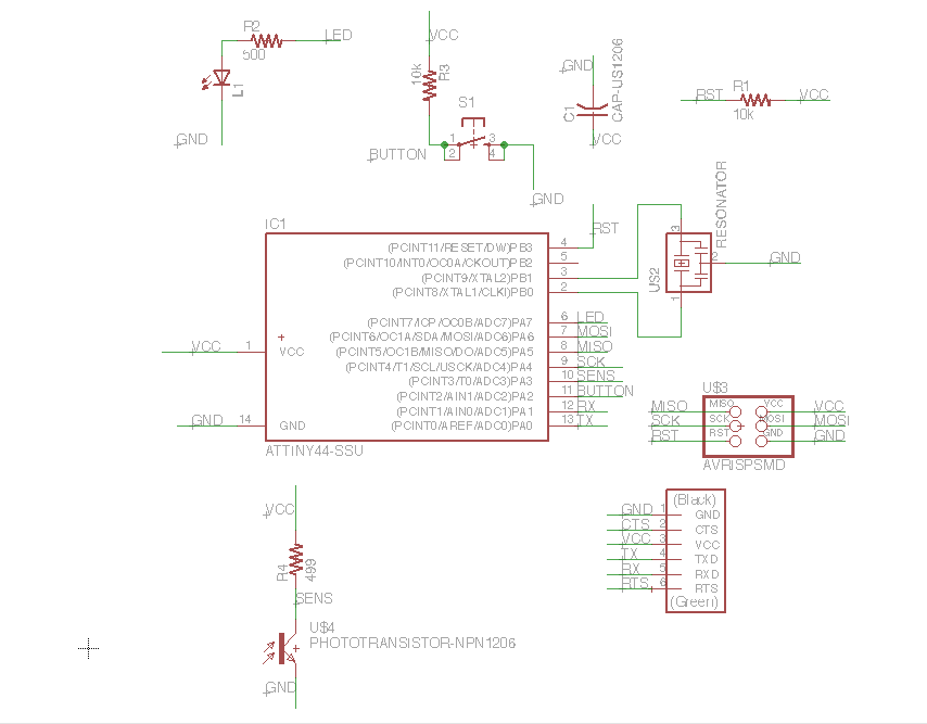
Step 1. Design the first board — with lots of input from Jean Francois (thank you!)

(4 hours of research and design — I know it seems like a lot but I still don’t quite get some of the basic electronics structure)

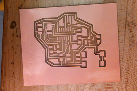
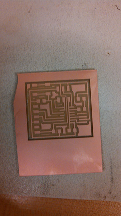
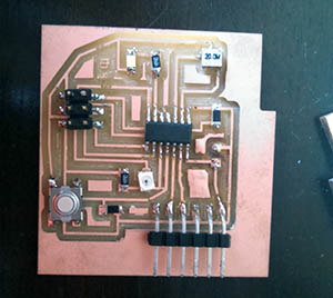
Step 2. Milled the first board and soldered it and tested the code.
It turns out the circuitry doesn’t seem to be working. Either that or it’s a bad mosfet connection. I tried resoldering every joint and replacing one or two parts. No luck. The code just never took.
I programmed using an Arduino Uno and the programmer was never able to speak to the microprocessor.

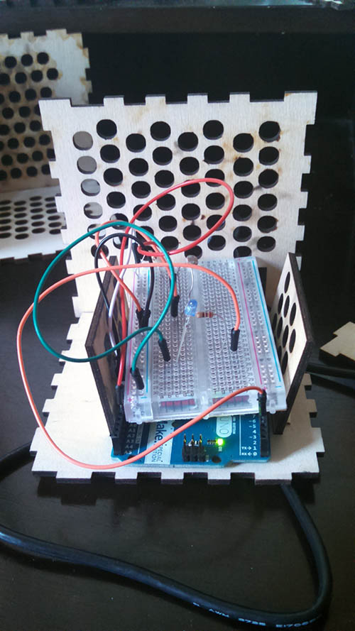
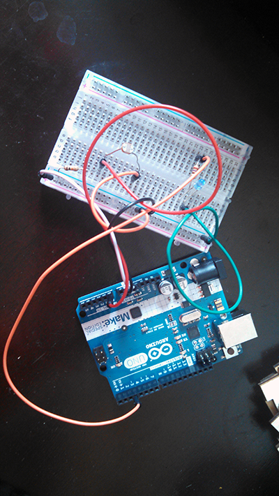
Step 3. Test electronics on a breadboard.
Jose and I worked together for a bit and tried the electronics design on a breadboard to see if we could get the basic design. The breadboard worked - so we felt good about moving back to electronics design.

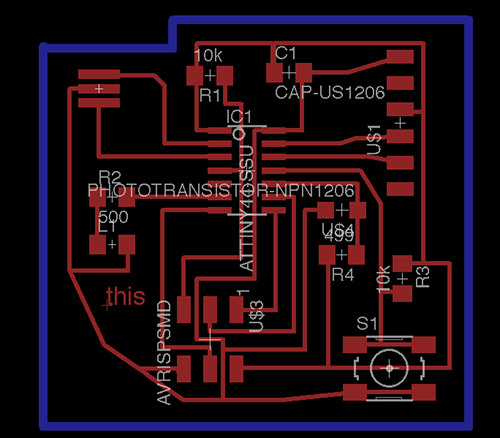
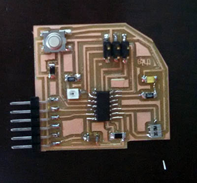
Step 4. Design another board.
The goal with this one was to make a super simple board and cut out the details like a 9 volt connection. If I could make something work that was simple, then I could move onto to something larger.
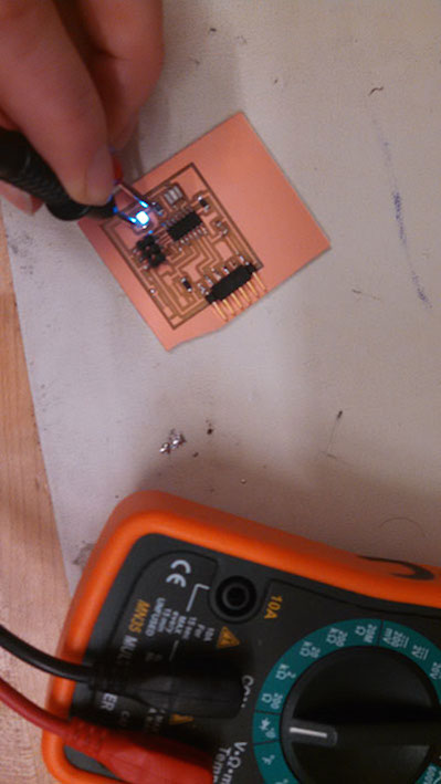
Project 15d Project 15e

Project 15f

5. Test board.
This one also didn’t seem to be read by the programmer - so we tested another programmer. Still no luck.

6. Try yet another board
This time I went back to a simpler design with a single LED, a button and a phototransistor.

Project 15g Project 15e

Board 1
Project 15f

Board 2
Project 15f

Step 7. Test the two board designs

I spent several hours working to tests the boards, test the different pieces and parts of the board. I tried resoldering all the boards to make sure it wasn't a soldering issue. The arduino would speak to the board - but the code never fully took.

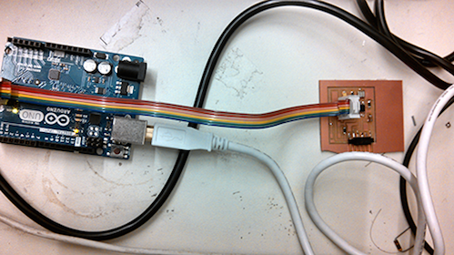
Step 8. Design another board - revert to Arduino.

At this point, I wanted to see if the electronics were possible using an Arduino. I used an Arduino and created the same concept -- which after some tweaking finally worked

The code used
		#include 

		int ledPin = 3;
		int threshold = 700;
		int sensorVal = 0;

		void setup() {
		  Serial.begin(9600);
		  pinMode(ledPin, OUTPUT);

		void loop(){
		  sensorVal = analogRead(A0);
		  Serial.println(sensorVal);
		  if(sensorVal > threshold) { 
		    digitalWrite(ledPin, HIGH); 
		  } else { 
		    digitalWrite(ledPin, LOW); 
		  }
		   
		 //slow down the transmission for effective Serial communication.
		 delay(100);
		}
	

Project 15g

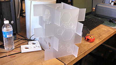
Step 9. Moved to the physical design again.

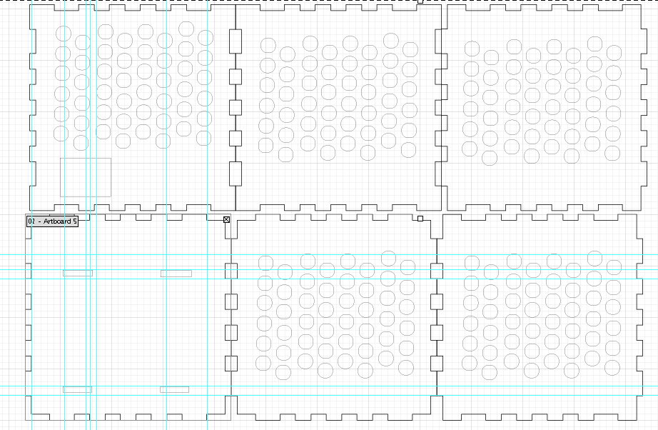
I had tried an earlier physical design using acryllic - which didn't work last semester. I learned a lot in the process. Number 1: making the kerf tighter than I expected given the size of the laser. This time I used cardboard again to first to design and iterate. the challenge is that the laser cutter must also adjust for the material. Once I got the cardboard working, I moved to the wood. I tested multiple designs. The first one I had a 0.1" kerf -- which was too much kerf. I then tested 0" kerf - which was too little. I tried 0.01" which was still too much. I finally landed on 0.0025" which was the right amount of give (diagram below).

Project 15g

Project 15g

Project 15g

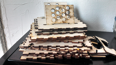
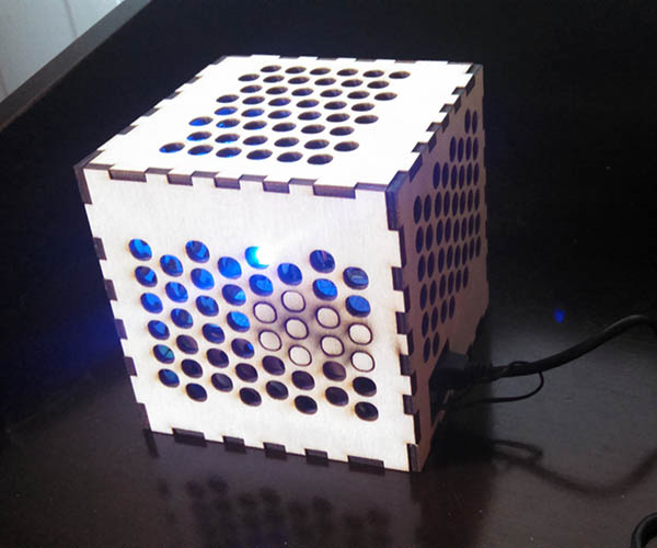
Step 10. Put everything together.

With plenty of hiccups on the way - everything finally worked - with a lot of help from an Arduino.

Project 15g

Project 15g

2014 Kate Mytty. This is under Creative Commons. Please do let me know if you use something.

Powered by Type & Grids