Basically, it is a box you keep outside in the cold weather that has a temperature sensor that lets you know whenever it is too warm out - i.e. when your meat would spoil, your icecream would melt or your beer would get warm. Originally, the plan was to have the PCB send a message to your phone via blue tooth or wifi whenever the temp rose too high; however, due to time constraints, that part was nixed. Now the functionality is simply to light up the red LCD when the temp rises too high. I designed the box in solid works. It is a hexagonal box to be milled out on the ShopBot and cut on the chop saw. Below is the base and lid.
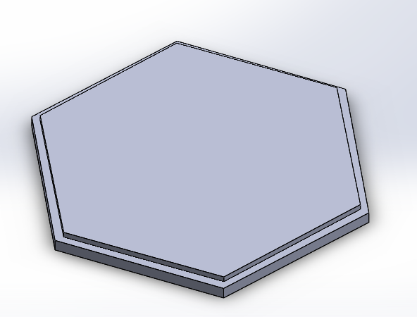
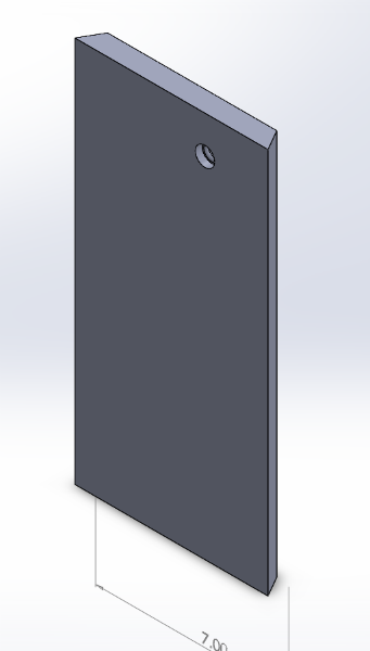
The six sides all have 60 degree angles to be cut on the chop saw. One of the sides, the front, will have a display for the PCB's LED.
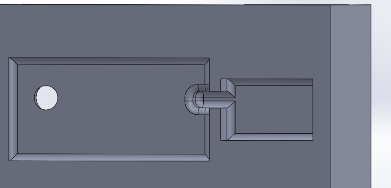
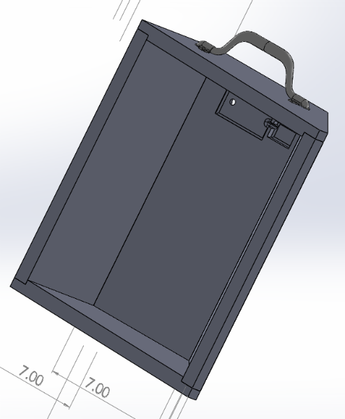
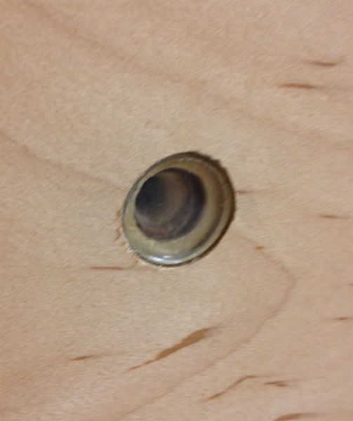
Here is an upclose view of the cutout for the LED. This is the outside of the box - the PCB will be fixed on the inside such that the LED is visible through this hole. The flat pocket is for an acrylic "window".

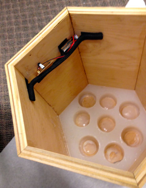
Here is the view on the inside of the same side panel, showing the pocket for the PCB and battery.
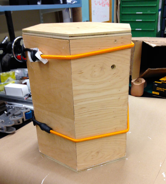
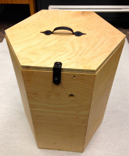
Here is the whole box.
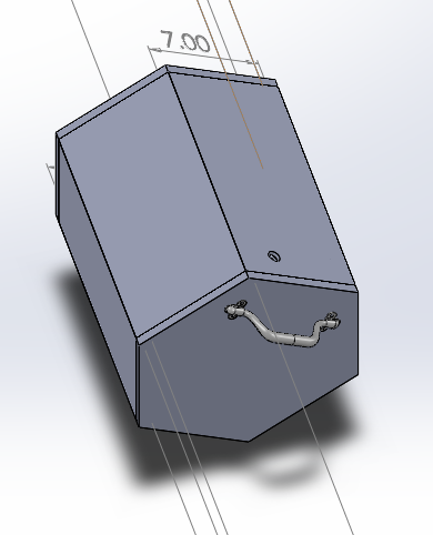
And a cutaway, just in case you still don't get the idea.
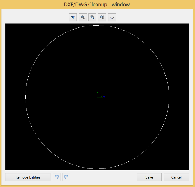
Here is the 2D DXF file for the "window".
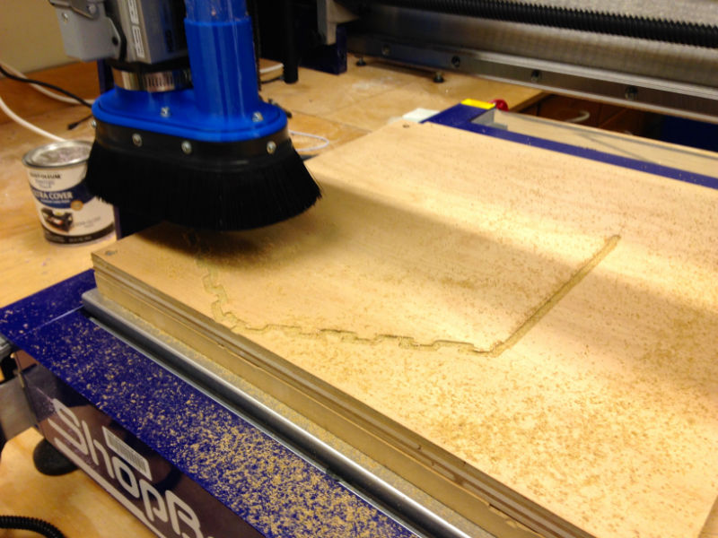
I cut the hexagonal base and lid on the ShopBot in GEAR lab, using Part Works 3D and the ShopBot software. Here is the ShopBot doing the first rough cut.
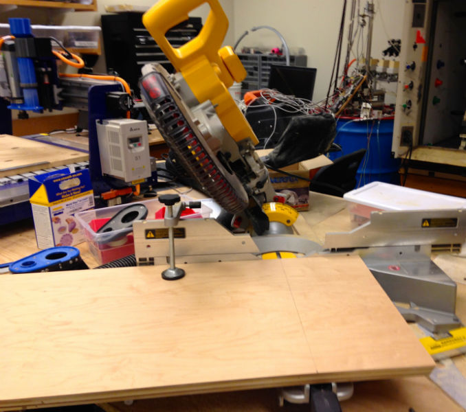
Below is the setup for cutting the 60 deg angle for the sides. The only real problem is that our chopsaw doesn't extend the full 14" of the length of the sides so there was a lot of switching the saw from left to right and flipping the piece to finish cuts, which led to some less than perfect cuts and a lot of sanding.
After cutting and milling and sanding all of the pieces, here they are all assembled waiting for the Gorilla Wood Glue (recommended to me by a 93 yr old man at Home Depot) to dry. The lid is just on to ensure alignment. I then nailed all the pieces from the base to strengthen it.
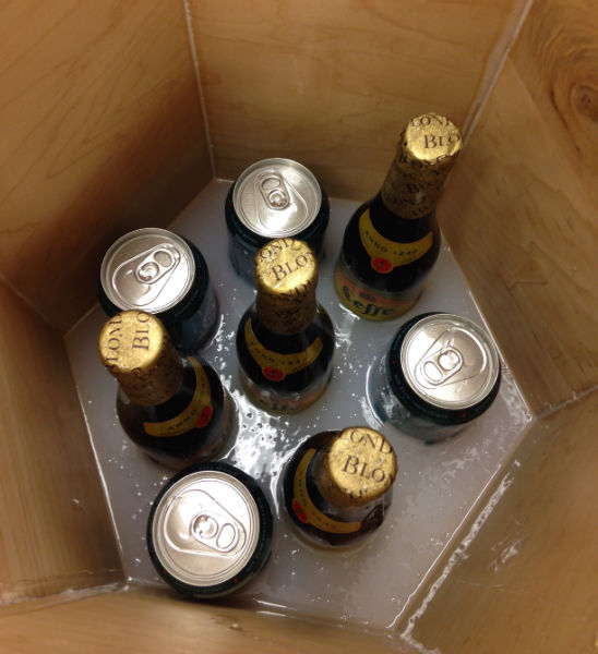
Next step was to cast the "cup holders". I used some real cans and bottles and poured in Dragon Skin Smooth On, which is supposed to dry in 10 min, but I had a very thick layer, so I left it overnight. Note, previously I had made sure to glue all the inside seams to prevent leakage.
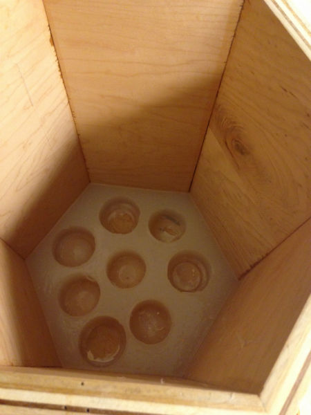
The "cup holders" after removing the cans and bottles. Unfortunately I did not put enough vaseline on the cans and bottles before pouring the silicone, so removing them required a little elbow grease and a small blade. Unfortunately, I pierced one of the cans with the blade, so that was a fun clean up. Also, left some imperfections.
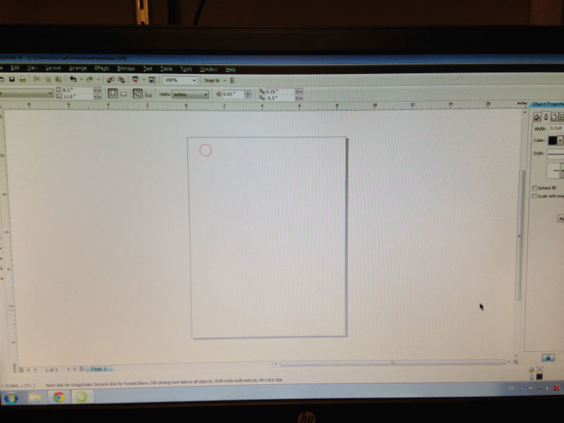
Next was to cut the window. Here is the super simple window DXF in Corel Draw, where I changed the line thickness to hairline and the color to red (req'd/BP for cutting on our laser cutter).
And here is the laser cutter cutting the window. Took ~10 seconds after zeroing and material selection/speed and intensity setting.
Here is the window over the hole for the LED display.
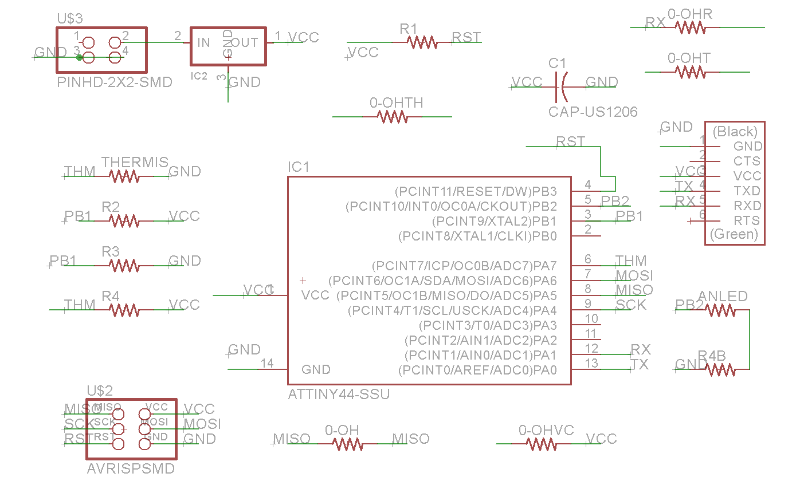
As for the electronics, again, the original plan was to have the PCB send a message to your phone via blue tooth or wifi whenever the temp rose too high; however, due to time constraints, that part was nixed. Now the functionality is simply to light up the red LCD when the temp rises too high. Below is the Eagle schematic for the board which uses a thermistor. For those of you who don't know (including me one week ago), a thermistor is a resistor whose resistance is very sensitive to temperature. Thus you can read the temperature by converting the electrical reading through the resistor times some coefficient of resistance.
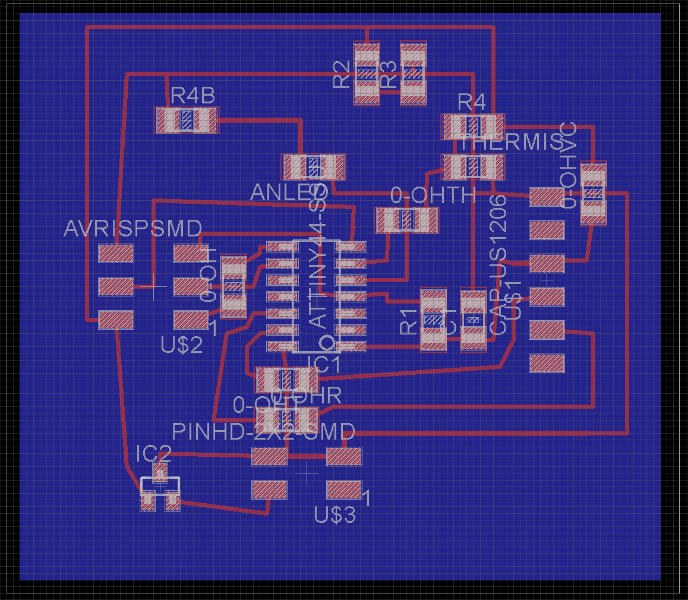
Below is the board view. There is a 9V battery to power the board so I don't need it to be attached to my computer. I used a 5v 100mA regulator to steady the power was coming through.
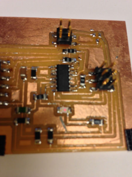
Below is the board all hooked up before installing it in the box.
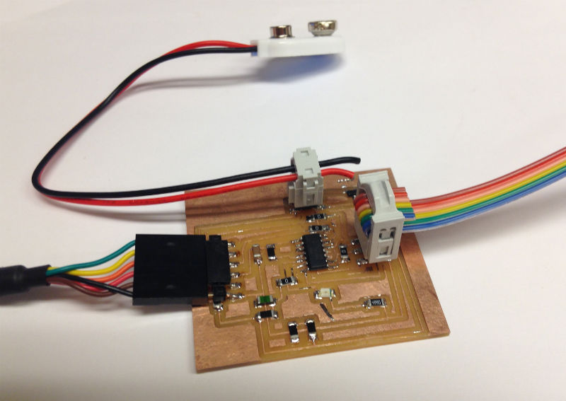
Here is the board and battery velcroed in (for easy removals for programming).
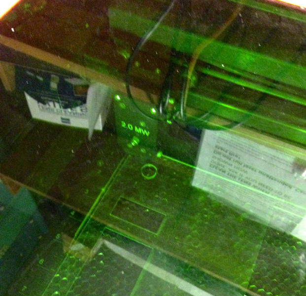
And here it is all together!
For the electronics part, the code is simple:
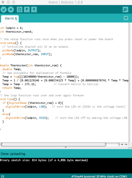
The only problem is that the LED doesn't shine very bright
All in all, the meat/ice cream/beer box is a SUCCESS!