
Week Four: CNC machining
Major thanks to Dan Chen for all his help this week, including showing up at 7 AM one day to be my shop buddy.
There is the perfect space in my room for a small sofa, but I haven't been willing to buy one. I decided to try making one this week.
I modeled the design after Kirstin Petersen's chair, which stood out at the end-of-semester demo night last year. Kirstin writes about the problems she had with the low-quality plywood sides buckling and eventually breaking, and she eventually remade it out of 1/2" birch plywood with much better results. So I may do the same eventually.
Instead of a wooden seat bottom/back like in Kirstin's design, which I don't think I'll have enough material for, I'm going to try using cord to make some kind of web between the side panels, and then put cushions on top of that.
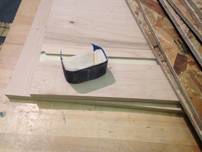
I designed the pieces in SolidWorks, drawing the curve of the chair back/seat by eye. It's hard to know what will be comfortable. Here's one of the three panels (the middle one, with six slots--the side ones will have only three each)
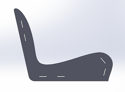
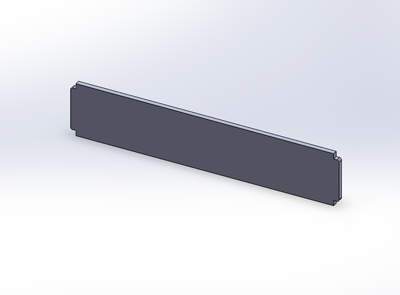
Slot tolerances were 0.010" for the length, 0.0125" for width (nominally, but the actual value depends on thickness of the stock. Since there's some variation, I checked that the sheets I was using were close to 7/16 to preserve this tolerance). Here's the crossbeam:
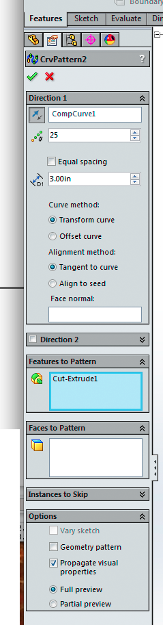
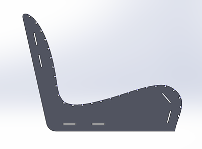
I also needed notches for the cord. My officemate Luke Mooney showed me how to replicate a single extrude all the way down the spline: turn the spline into a composite curve first; then do a single extrude for the first notch; then in the Features menu, under the linear patterns icon, choose “pattern from curve”; click into the Direction field and click on the composite curve to use this as the curve to follow; then under Features to Pattern, pick the cut-extrude. Set the number of repetitions, spacing, etc.; choose options as shown. If nothing appears, try clicking on the arrow button next to direction to point along the curve in the right sense.

I decided to use Inkscape rather than SolidWorks to lay out the pieces as they'd be cut on the material. It was more trouble than I expected getting the size/image type/stroke width to be imported and saved correctly in Inkscape, and it would have been easier to put the DXFs from SolidWorks straight into PartWorks down on the ShopBot computer and lay them out there. The one virtue of doing it ahead of time was that I could use my couple of hours on the ShopBot more efficiently (cutting takes a long time!).
Exporting to DXF from SolidWorks is easy. There are a few ways, but I found Matt Carney's suggestion easiest: turn the sketch you want to export into a face by extruding it if you haven't already; select the face by left-clicking on it; then right-click and choose the "Export to DXF/DWG" option.
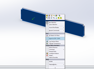
In one of the windows that come up in the export sequence, you will see the layout you're exporting. You can select and delete elements of it here if you like. I used this option to create the two side panels (with three slots each) from the single middle panel design (with all six slots).
I used PartWorks (on the ShopBot computer) to create toolpaths from the DXFs, one for each of the two sheets of OSB I was going to use. I stuck to the settings Tom recommended for this project: 0.25" end-mill, 10000 rpm, feed speed 160, ~0.52" cut depth (for the ~0.44" stock) in two passes (using the rule of thumb that you don't cut deeper than the diameter of the tool on a single pass).
I noticed that my toolpaths were switching from one side of the vector to the other, and realized that what looked like a single vector in my design was really several. Will Langford explaind how to fix this in PartWorks: "You can use the "Joint Vectors" operation to combine the line segments. Select all your lines and then go to edit --> join vectors and then select a tolerance (maybe 0.001"?)."
Also in PartWorks, I added 0.1"-wide, 0.26"-deep tabs at spots I chose manually. (These settings ended up working well. The tabs broke easily when I took the pieces out of the stock, and not before.)
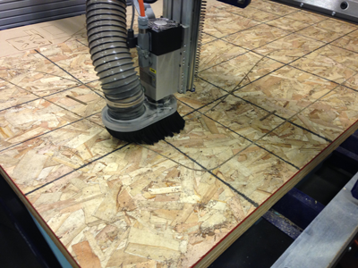
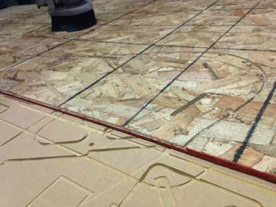
Cutting out a side panel:
It turned out that the origins of my DXF files were not actually at the origin of the ShopBot's workspace. (Check this when you first load a file into PartWorks! There is a box checked by default that tends to move it around. The origin is set to the intersection of the gray crosshairs, not to the corner of the black box.) This turned out to be a big problem. As you can see, I got lucky with this side piece and it just barely fit:
But later on, the end mill got too close to the far end of the board, hit one of the screws holding the board down, and broke. If I'd been watching the cut at the right moment instead of looking at the parts I'd just taken out of the last sheet, I would have noticed before it happened.
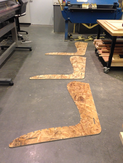
Other than that it came out correctly. Here are the three panels:
This was Didi Vardi's useful suggestion for sanding more easily:
The crossbeams fit pretty well into the slots. It was easiest to fit them in when I filed a slight chamfer into the edges of the slots. I glued them in place:
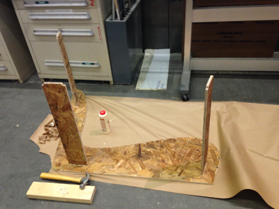
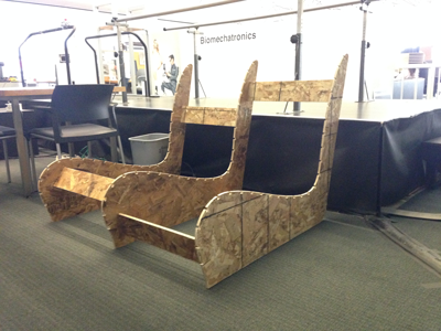
Here it is coming together:
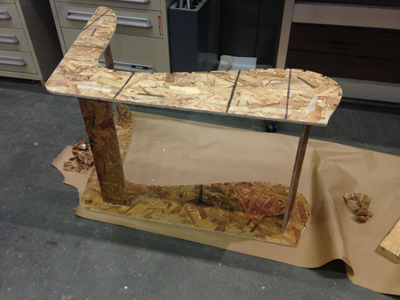
...and upright:
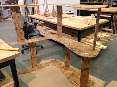
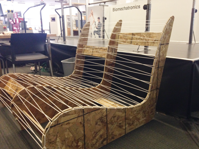
Adding some nylon cord:
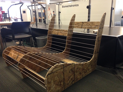
And some more:
Finally I put an egg-crate mattress over the web of cords as a cushion. Here is my labmate Shuo modeling it. I'd like to sew a cover for the egg-crate mattress, with ties to attach it to holes I'll drill in the side panels or some other way to keep it in place.
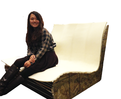
The shape is pretty much what I wanted. It might be comfortable to sit in if I weren't so afraid it would break. Even if I sit down in it really gingerly, the sides buckle slightly and make me nervous. One thing to try would be adding some more cord on the bottom, or some more crossbeams closer to the top under the seat, but a better solution might be to follow Kirstin's lead and use a nicer (and a nicer-looking) material.