
Week Nine: Input devices
Thanks to Jeff for answering my questions this week.
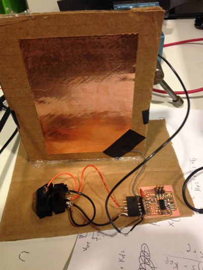
This week I wanted to make a capacitive proximity sensor to use for volume control in my final project. I imagine that you would increase the volume by putting your hand on one side of the case, and decrease the volume by putting your hand on the other side, with duration of the touch controlling the change in volume.
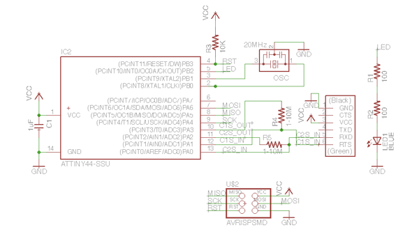
As a pad, I'm planning to stick some copper foil onto a piece of cardboard for now as a mock-up of what will be in the case. C1S_OUT will set a test voltage, and C1S_IN will measure the voltage at the pad. (There's also room for a second sensor.)
I'm using the ATTiny44 for this, and I've taken over some of the communication pins on the FDTI header for sensing (this makes the layout easier), with the idea that I can use the scope to see changes in capacitance.
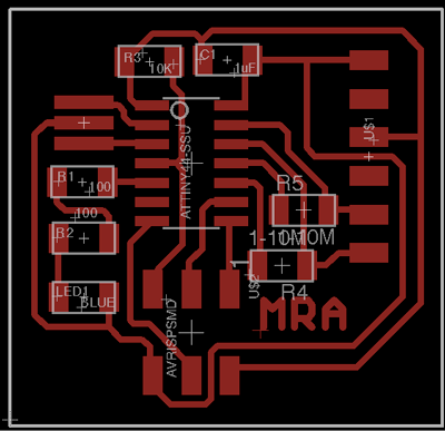
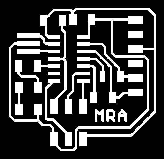
Here's the layout. Again I increased the outline width to 19 pixels so that the fab module would create a path.

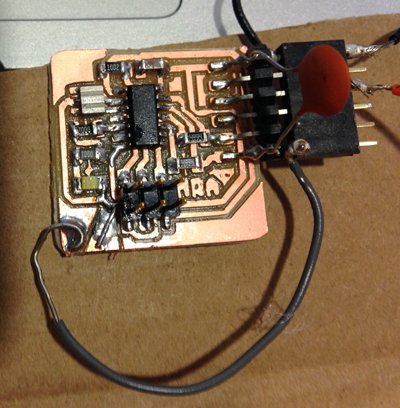
The board works:
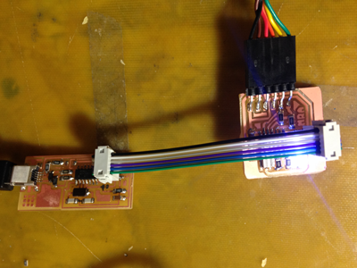
I replaced the FTDI cable, which is only providing power right now, with three button cell batteries and a switch for convenience.
Here C1S_IN is connected to the pad (and C2S_IN is connected to nothing for now). On the other side of the cardboard is another piece of foil that's grounded. I'm toggling the C1S_OUT pin at 5 Hz and looking at the voltage at C1S_IN.
The resistor in series with the pad is 5MOhms. I also bypassed the sensing pin with a 0.47nF capacitor which got rid of some noise.
My expectation is that at 5 Hz, the pad voltage should have settled to the test voltage by the end of each half-period, and I'm testing this by having the LED show the state of C1S_IN. So I'd expect to see the LED turning on and off at 10 Hz.
This happens when I have a scope on the sense pin, but not when I don't--which could mean that the capacitance between the pads is too large, although it's not clear how the scope could decrease it.
Here I've moved the pads onto some spare copper on the board. This version does what I expect--the LED blinks at 5 Hz when I put my finger close to the pads.
There's a lot of 60 Hz noise on the scope reading, which makes it hard to see the step response of the sensor and see how much the capacitance is changing.
At this point it would really be helpful to have a way to communicate with the ATTiny to see what's going on without the scope, but I'll need to make another board for that.