Week Ten: Output devices
This week I started thinking about the switching audio amplifier for the speaker I want to build for my final project. Since I’ve never built a speaker from scratch before like this, my expectations are pretty low. It will be nice if it works.
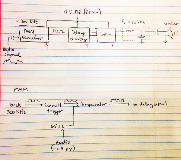
Here's the general plan:
First I want to choose components. What I need will depend on how much power the amp will have to handle. How do I know how much power my speakers need? Here is a quick guide to how to answer that question. It depends on the sensitivity of the loudspeaker itself (the part after the amp). Sensitivity is measured in dB per [Watt per meter], meaning volume a meter away with one Watt through the loudspeaker, for audio signal at e.g. 1 kHz).
But I haven’t made the speaker yet, so how can I estimate its sensitivity? This site says most commercial speakers are in the range 84-90 dB. A human speaking voice gets up to maybe 70 dB. So let’s say a sensitivity of 70 dB is a reasonable goal for a DIY speaker made out of balsa wood, being conservative. An increase of 3 dB is about a 2x increase in power. So to get 105 dB sensitivity (the highest we’d EVER want, comparable to movie theater audio systems, but this seems to be the way people on the internet talk about choosing power levels), we’d need 2^((105-70)/3) = 1.625 kW...!
That’s clearly not a helpful way to think about this. Let’s aim for 10 W, since a commercial speaker might be in the 40-50 W range, and most of the time we won’t be using more than about 1 W anyway, based on what I’ve been reading.
Here are the MOSFETs we have in the inventory. There are two N-channel FETs. The 1.7A one is not going to do the job. Can we use the 16A one?

How much current will they need to handle? Let’s assume we’ll have a 12V source (a power supply initially, maybe batteries + boost converter later if there’s time). Then maximum current will be 10 W/12 V = 0.83 A. So the 16A FET will be fine.
What about heat? Looking at the datasheet, the absolute maximum temperature for this FET is 150 degrees Celsius at the junction. So at 25 degrees ambient temperature and without a heatsink, it can tolerate at most a 125-degree temperature rise. The junction-to-ambient thermal resistance is 100 degrees C/W:

That means this FET can’t dissipate more than 1.25 W without overheating without some kind of heatsink (which we could add, but first let’s see if we can do without it). Rdson, the drain-source resistance when the FET is on, is 0.047 Ohms, so conduction losses (I^2*R) at 0.83 Amps are 0.0323 W, well below that, and we can expect ~3 degrees temperature rise due to conduction losses.
How high a switching frequency can we handle with these FETs? I still haven’t decided what range this speaker will cover, but if we wanted to make a tweeter with good response all the way up to 18 kHz, we’d need to be switching at least an order of magnitude faster than that (180 kHz), preferably higher, so that there’s enough room in between for an LC filter with good attenuation at the switching frequency and without resonating at some audible frequency, AND without needing tight tolerances on L and C.
Let’s sort of arbitrarily say we can tolerate 0.5 W total switching and conduction losses in the FETs. That way the amp will be at ~ 66% efficient at 1 W output, ignoring the control circuitry. That leaves a budget of 0.5-0.0323 = 0.47 W for switching losses.
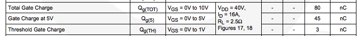
If we are using a gate driver that can supply 1 A, and Vds = 12 V, then switching losses are (½) 1*12*ton , where ton = Qgs / 1 A = 45 nC / 1e9 nA = 45 ns , so with two FETs we lose 2* ½ * 12 * 1 * (45e-6) = 0.540 uW per switch, or 1.08 uW per period.
That means we can tolerate a switching frequency of 0.47 W/1.08 uW = 435 kHz with this choice of mosfet, without a heatsink, which is high enough.
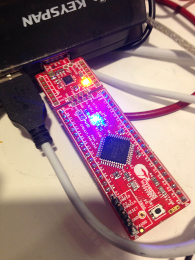
I also started experimenting with a PSoC this week after a short demo on it in another class. I'm hoping to get more practice by using it for the PWM and delay circuitry: