This week I worked towards my proposed final project by building a “cube” in the assembly. Each cube can fit together with magnets to form a larger furniture piece.
This was my first attempt at using SolidWorks. I used the “Master Model” approach – which means creating one “master sketch” with the entire design and deriving each part from that master sketch.
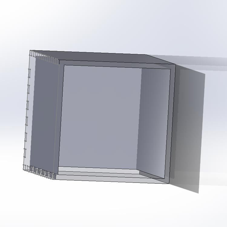
Here is the final SolidWorks assembly, which includes dovetail joints between faces and holes for the connector magnets:
 |
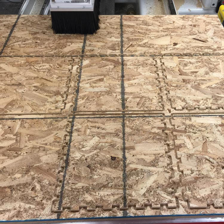
I exported this to .dwg format by using the “create drawing from part” command in SolidWorks, and imported the 2d file into Rhino where I made some final edits for CAM. To prevent chamfer at the corners of the dovetail joints, I created small holes at each 90 degree turn in Rhino. I imported the final .3dm file into Mastercam and sent the job to the mill:
 |
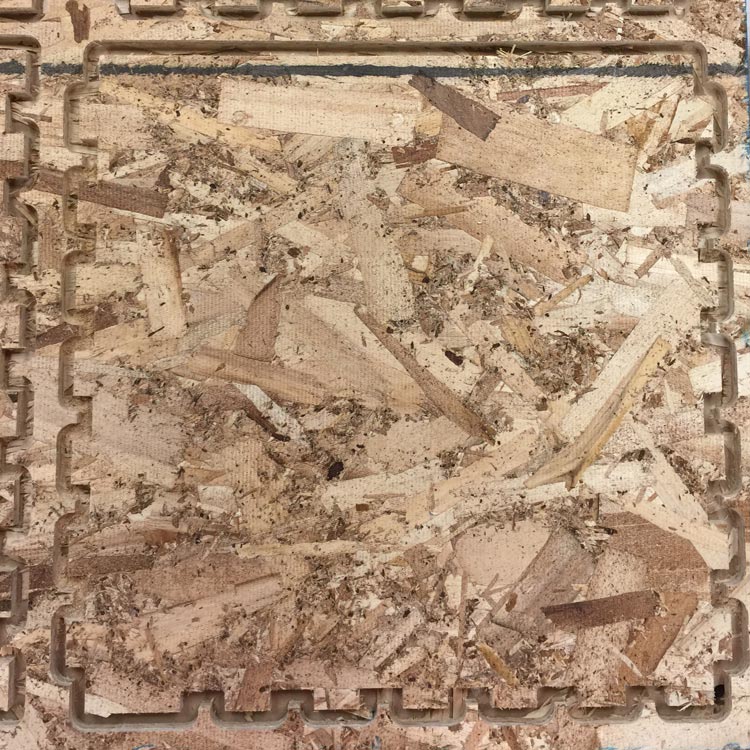 |
I ordered some magnets and they fit nicely into these cuts:
 |
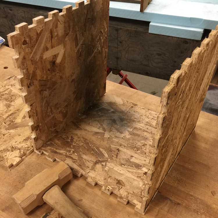
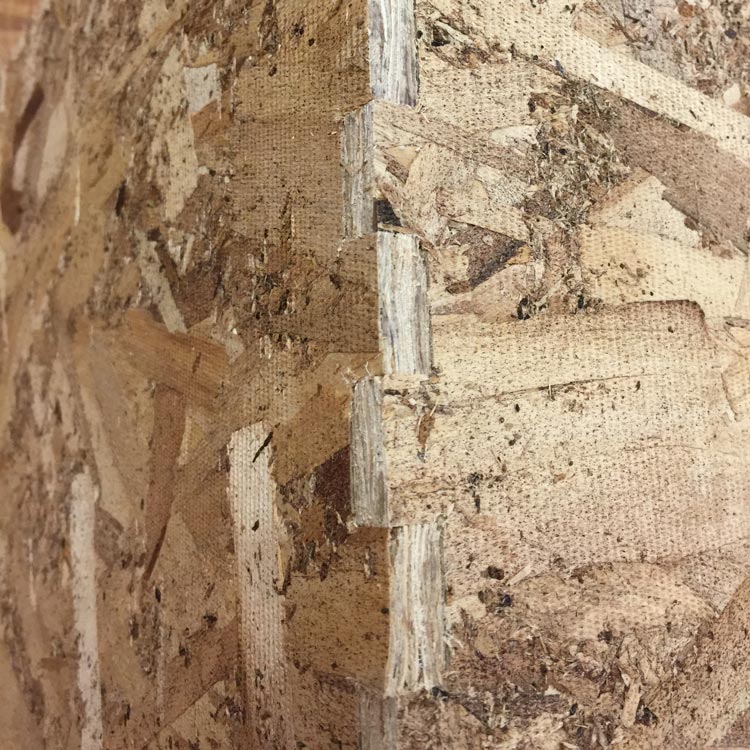
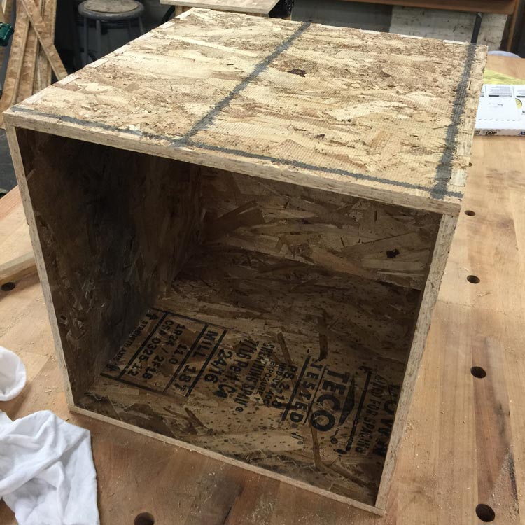
All that was left to assemble the cube. Nothing that a mallet couldn’t solve!
 |
 |
 |
I am looking forward to building more cubes and seeing them connect with magnets. The best part is yet to come – electronics!