For my final project I decided to make a proximity activated light
desk. Using a step response sensor, the desk activates when someone
begins writing/drawing on the desk. Then a charlieplexed array of
lights turns on and provides a backlight to the desk. The purpose of
the light is to provide contrast when using dry erase markers
directly on the desk or to provide a backlight for sketching/tracing.
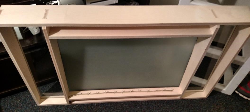
Designing the Structure
I designed the structure in SolidWorks around a piece of glass that
I already had. I designed the desk so that it would have a small
groove that the glass could slide into. The glass was 3/16th
inch thick so I made the groove 0.2 inches thick to give it
a small gap which worked perfectly!
For the rest of the structure I used press fit tabs with 5 mils of
clearance around all the tabs. This clearance provided a very snug
fit that was easy to assemble.
Milling the Structure
I milled the plywood for the desk on the Onsrud in the Architecture
wood shop but this proved to be extremely difficult. I faced
pretty much every problem you can have:
1. The Onsrud was incredibly busy since Arch majors were finishing
up final projects, so it took me three days to cut my material
2. Initally I had left too little material in some areas in my
SolidWorks design which Chris Dewart caught so I had to go back
and redesign it
3. We accidentally chose the wrong end mill in MasterCam and only
noticed this after we started the job which we had to abort to
avoid breaking the end mill and switch to the correct tool
4. We left out an onion skin or tabs on the material so toward the
end of the job the material shifted ruining the entire sheet of
plywood
5. I also noticed at this point that we had chosen an end mill that
was too big (3/8th inch) because it wasn't able to reach
small areas.
6. After buying a new piece of material we accidenatlly put one of
the parts too close to the edge so it moved and was misshapen so we
had to repair it on the band-saw
Finally at 1AM on the third day of being in the wood shop the parts
were successfully cut out and it all fit together incredibly well!
I have to give a special thanks to
Enas Alkhudairy,
who spent hours helping me set up my MasterCam file and keeping the
shop open to allow me to finish my job.
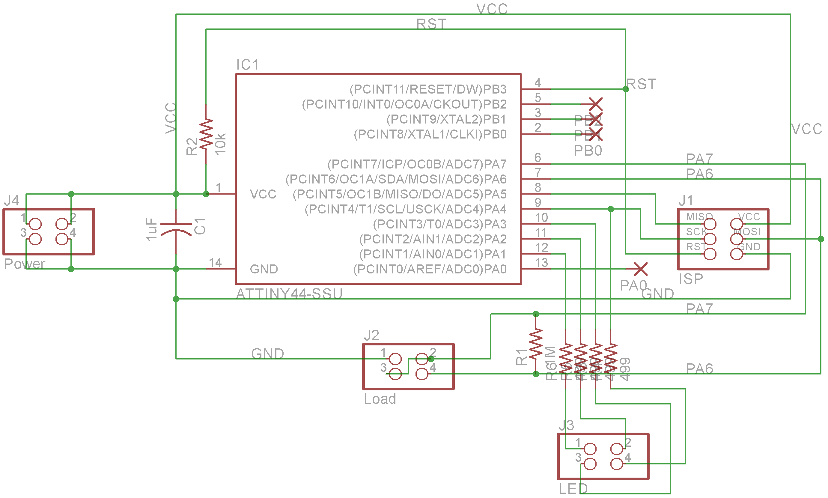
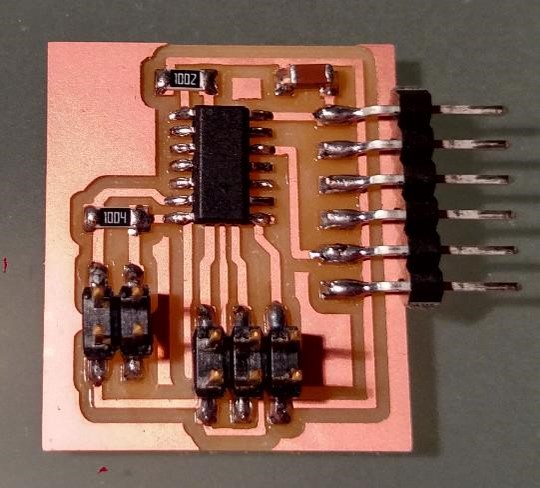
Designing the Circuit
I designed a circuit that is a combination of Neil's charlieplexed
array and step response load boards. I used an Attiny44 to have
enough pins for charlieplexing and step response sensing.
Instead of having the Charlieplexed LED's on the board I wanted to
be able to design and connect them as an external output device.
To do this I added a 2X2 header jack. My plan was to take a long
4-strand ribbon cable setting each strand as an individual pin.
Then I could solder the LED's direcctly onto the ribbon cable
making a linear strand of charlieplexed LED's
I also added a 2x2 header for the power supply so that I could
plug a slightly modified AC power adapter into the board. I chose
to leave out the 5 volt regulator and just make sure that I only
used a 5 volt power supply.
Finally, I added pads to any unused pins in case I need to hack up
my circuit later or add functionality. Everything else on the board
is pretty much directly out of Neil's boards.
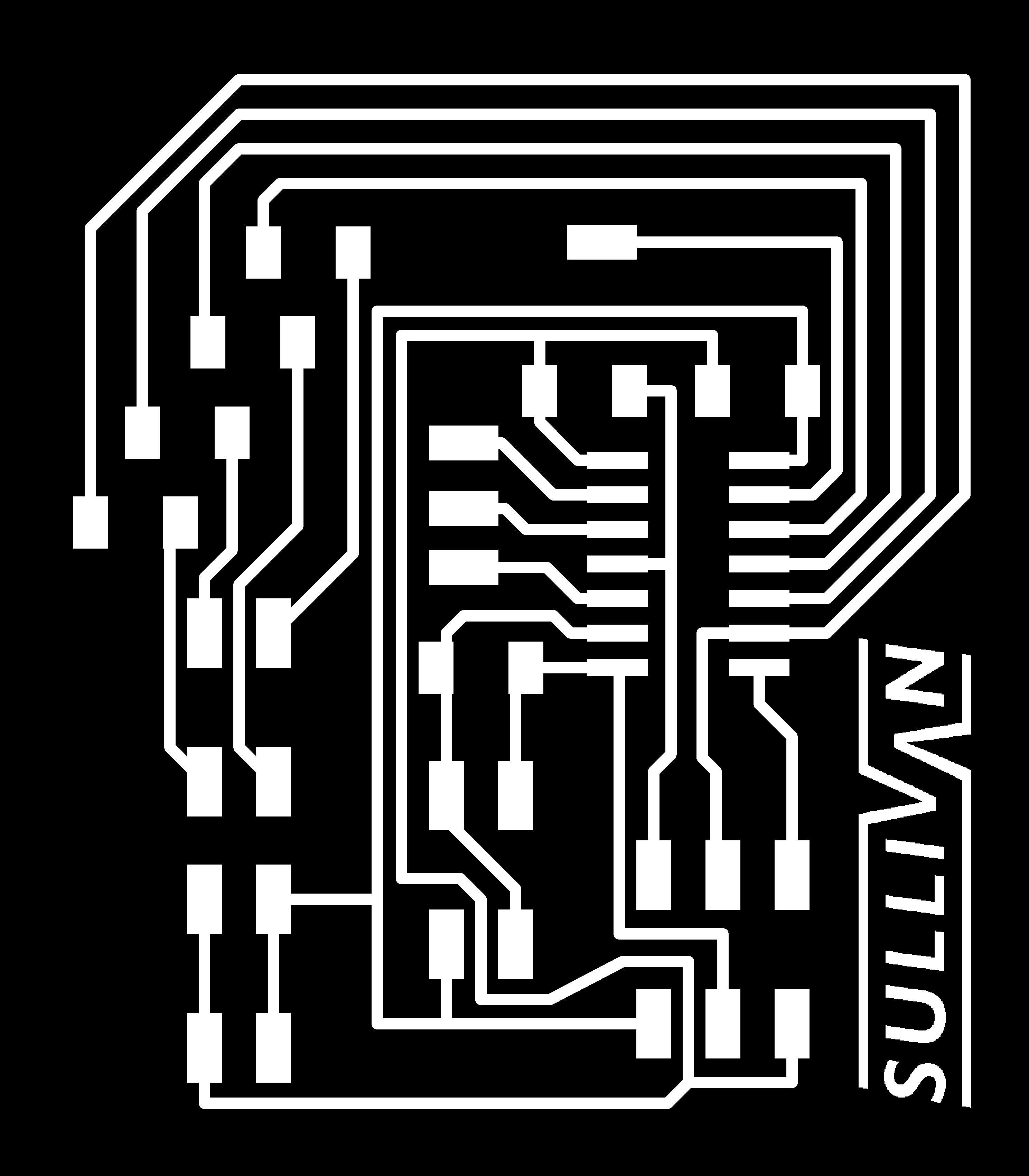
Traces
Cutout
Making the Charlieplexed Strand
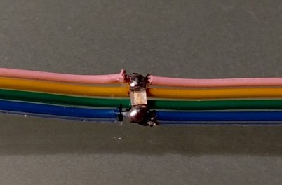
To test if the charlieplexed strand would work I soldered 12 blue SMD
LED's to a 22 inch strand of ribbon cable. I was worried that the
solder joints wouldn't be very robust but it actually worked very
well!
In the image the pink strand corresponds to pin 12 on the Attiny44,
yellow is pin 11, green is pin 10, and blue is pin 9.
It was expectedly difficult to solder each LED to their
corresponding strands but I was able to get all 12 of them working
independently.
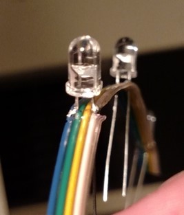
You can see in the video above that the blue LED's weren't bright
enough to light up the entire table so I went to RadioShack and
bought some "superbright" white LED's.
Using the same method, I made a another charlieplexed ribbon with
the new LED's:
This new strand was significantly brighter but it still wasn't
as bright as I wanted. There wasn't much I could do about it at
this point since I bought the brightest LED's that they had in
stock at RadioShack (they didn't have anything bright enough at
Microcenter).
Nevertheless, the ribbon method seemed to work nicely!
Diffusing the Glass
To make the glass more opaque so that it could diffuse the
backlight I bought some glass frosting paint. This worked pretty
well. It was opaque enough to block out images behind it while
still allowing most of the light to shine through.
Programming
This was the most difficult part of the entire project for me.
Coding the charlieplexing in arduino was very simple and I
thought I would have no trouble simply adding the step response
code to my charlieplex code. I was very wrong.
I realized that I didn't actually understand fundamentally what
was going on in the step response circuit so I had no idea how
to begin coding for it. I looked through everyone's page from
the previous year but I wasn't able to get any Arduino code that
worked for me. This was when I realized I needed to learn how to
program in C if I wanted to use Neil's code. This took a while
but I finally learned with help from:
Once I had figured out how to program in C, I actually realized
that I like it more than using Arduino (it might just be
because there are more examples available).
Now I was able to combine Neil's charlieplexing and step response
codes to program my board! Wrong. I still couldn't get anything
to work with my board so I thought I needed to go back to the
basics and work my way up.
As a result I decided to try and remake Neil's hello.load.45
board but simply switch it with an Attiny44 which you can see to
the right. I thought this was simple enough and I was hoping that
I could at least get something on the Serial Monitor with this
board
Of course I was unsuccessful and I couldn't get any response. I
realized that I was doing something wrong in trying to adapt the
code for an tiny44 so I decided to just make Neil's board as
designed (left) and see if I could figure out what each line of
the code was actually doing.
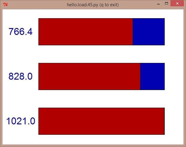
Finally, after using Neil's board, makefile, C-code, and python
script I was able to get a response:
Now that I had gotten a board to work I messed around with the
code to figure out what each line did. This really helped and
finally I was able to understand what was going on.
Then I altered the code to work with the tiny44 with help from
Matt Blackshaw's Page,
and I added the charliplexing code and it worked!! Here's my
code:
In my code I define the pins then tell the tiny44 to check the
step response pin. If the value on the pin is below a specified
value the microcontroller activates the LED's and holds them on
for a specified amount of time. If the user leaves the table
then the lights will dim to indicate that they're about to turn
off and then finally turn off. If the user stays at the table
then the lights will remain lit indefinitely.
One very important thing I found out was that you can make the
charlieplexed LED's brighter by turning multiple on at a time
instead of cycling through them individually. I did this by
turning on all of the LEDs that share a common anode at one
time. For example, you can make pin A your anode while pins
B,C, and D can all act as cathodes. So you light up 3 LED's
instead of 1. I used this to vary the intensity of the lights.
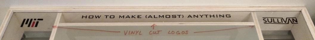
Using the Vinyl Cutter
In the end I thought I'd add a few stickers to make the desk look
a little nicer. This was the second time I'd used the vinyl cutter
and the first time I had to use transfer paper and I found out that
the vinyl cutter would only work when I set the origin to the bottom
left in the fab modules.
I also learned the how to use the transfer paper after kind of
messing up the first two attempts. If you use the transfer paper
don't separate the image from the scrap until the very very end when
everything is adhered to the final surface. In other words, do it
in this order:
1. Stick the transfer paper to the vinyl cut image
The thing that I'd like to change most about the project is
the strength of light. During the day it's difficult to
even tell that it's on. I also wish I could have learned how to
fade the LED's in an out but this proved to be more difficult
than I realized with charlieplexing. I also wish I had added
more functionality to the desk but I ran out of time.