Week 2: Printed Circuit Board Fabrication
This week we made a printed circuit board using a small CNC mill.
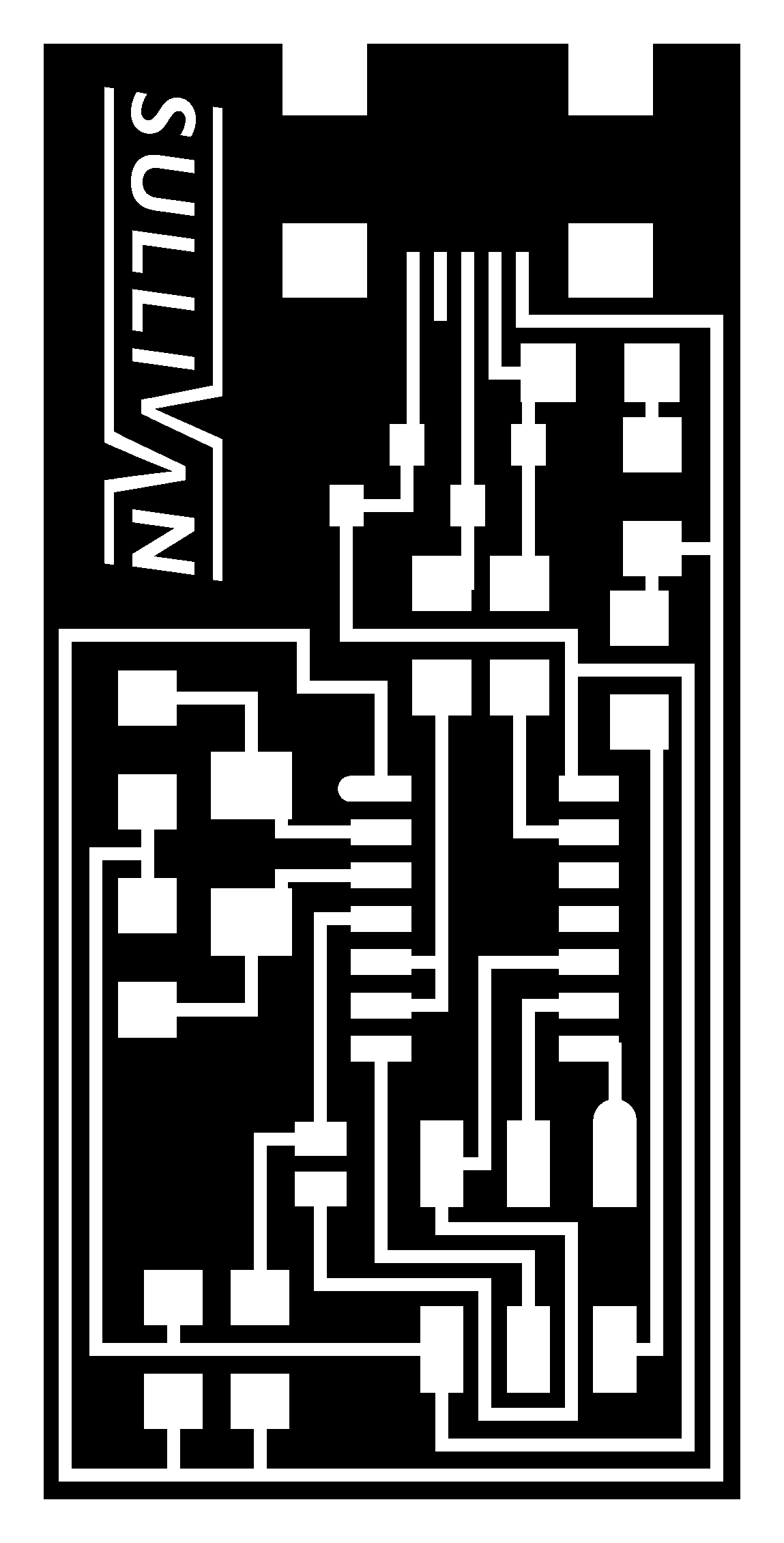
Personalizing the Circuit
Using the basic PCB design, I added a small logo to board using Microsoft Paint.
After uploading the image to the fab module I noticed that my logo was too
small for the mill to cut out properly. So I went back and edited the logo
so that the lines were far enough apart that the 1/64
th inch bit
could fit between them.

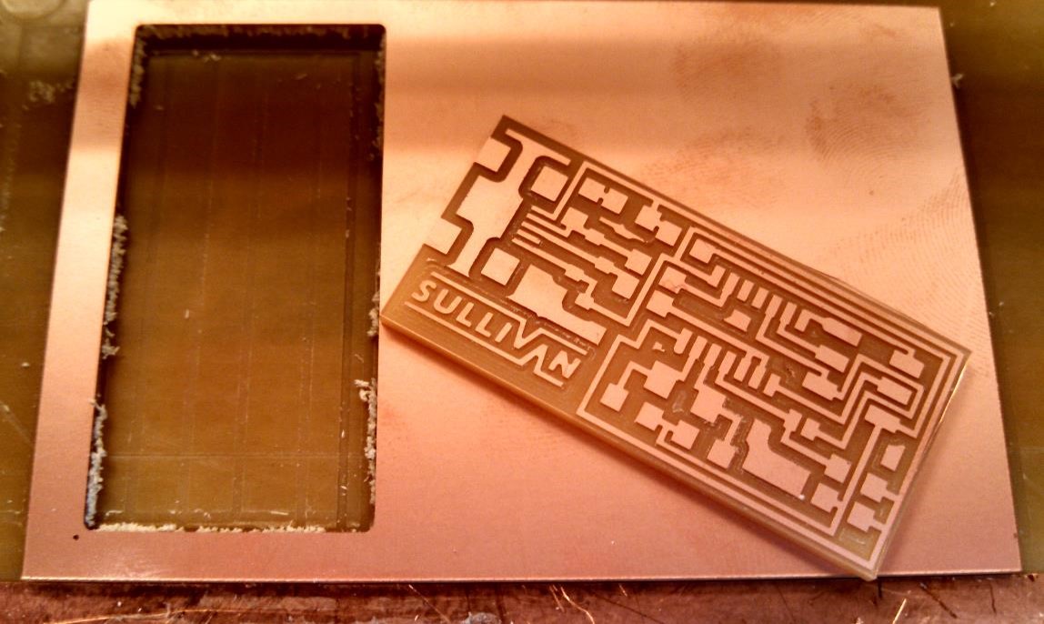
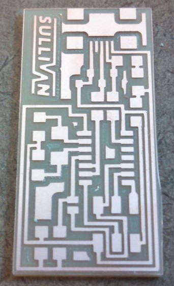
Milling
MIlling was fairly straightforward. Here are some things to remember:
1. Remember to set the command line in the fab module to ".../ttyUSB0" or
nothing will happen.
2. Make sure the dimensions (listed
under "input" on the fab module) of
the "traces" and "interior" files match.
3. Make sure that if the clear mill hood is removed you have something to replace
the safety switch.
4. Make sure that before you cut out the "traces" you press the "Down" button a few
times or the mill will just scratch the copper surface.
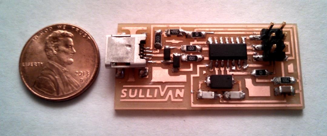
Soldering
Soldering was by far the trickiest part of this assignment. It took me a while to get
the technique down but I realized that the solder seems to favor the components rather
than the copper on the board. In other words, the solder balls up on the board but
sticks pretty well to the parts.
To fix this I started heating the copper before placing the components on. This made the
solder more willing to wet the copper surfaces which made the soldering much easier.
Another piece of advice is to be very careful with the board when it's hot. The adhesive
that attaches the copper to the bottom layer seems to be much weaker when it's hot. I
accidentally melted one of the mini-USB-port's pads off by heating it too much
(and probably being a little too aggressive).
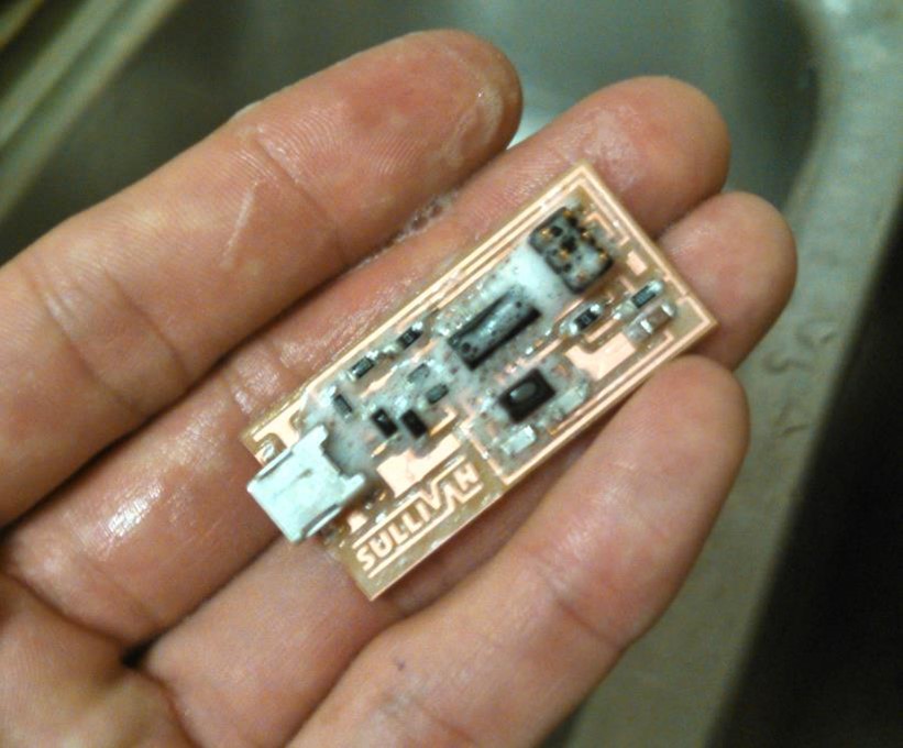
After you're done soldering, make sure to clean it well with soap and water because
the flux seems to tarnish the copper pretty rapidly.

Programming the Board
There are five main steps to getting your board programmed:
1. Use a multi-meter to check for accidental solder bridges or lack of essential
connections.
2. Plug the board into a USB port and measure the voltage accross the power and ground
of the 2X3 header component (should be around 5 volts). If you see blue smoke or smell
burning electronics at this point something went wrong.
3. Attach the AVR programmer to the 2X3 header. If you see the red light on the programmer
turn green then your board is working! If you see a flashing orange light you
most likely have the 6-pin ribbon on backwards. If the light stays red something is
wrong with the circuit. Check again for solder bridges or unconnected traces.
4. Then follow the programming instructions very carefully.
5. Remove the two jumper resistors.
Mistakes I Made
The biggest mistake I made was being a little to forceful with the copper trace
when I was soldering. Thinking that I was keeping the solder in liquid form I tried
to adjust the USB port but instead I accidentally peeled the copper pad off the board.
It was surprisingly easy to do so I suspect that I had heated the pad so much that I
weakened the adhesive holding the pad down.
The other mistake I made was not washing the board thoroughly enough after soldering.
Now the board is already pretty tarnished after only a few days.
This final note is less of a mistake and more of bad practice. The first things I
soldered to the board were the difficult components (USB port, attiny, etc.). This was
a bad idea because I still hadn't gotten the technique down. I thinks it's smarter to
start with the easy stuff, like the diodes, then move on to the harder components when
you get the hang of things.