Week 9: Input Devices
The objective for this week was to add a sensor to a
microcontroller that we design and then read the input from that
sensor. I chose to make a temperature sensing board.
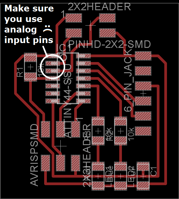
Designing the Board
I used Eagle to design my board using Neil's
temperature board
as a reference.
My plan was to make a board with an external sensor attached by a
cable so that I could measure a relatively remote temperature. To do
this I decided to make the NTC and wheatsone bridge connect to the
microcontroller through a 2x2 pin header.
I also wanted to add a blue LED to indicate that the measured
temperature was cold and a red one for warm temperatures. This
required a microcontroller with more pins than the ATtiny45 used in
Neil's board, so I used the ATtiny44a.
This was great except that I didn't get the pins right when I
attached the sensor and I accidentally connected the NTC to two
digital pins. As a result, the microprocessor couldn't measure the
analog voltage from the thermistor.
Sadly, I only figured this out after milling and stuffing the
board. This meant totally redesiging a new board. In order to
quickly fix my design I had to drop the red led. Below you can see
all my different Eagle designs.
-
Failed First Design
-
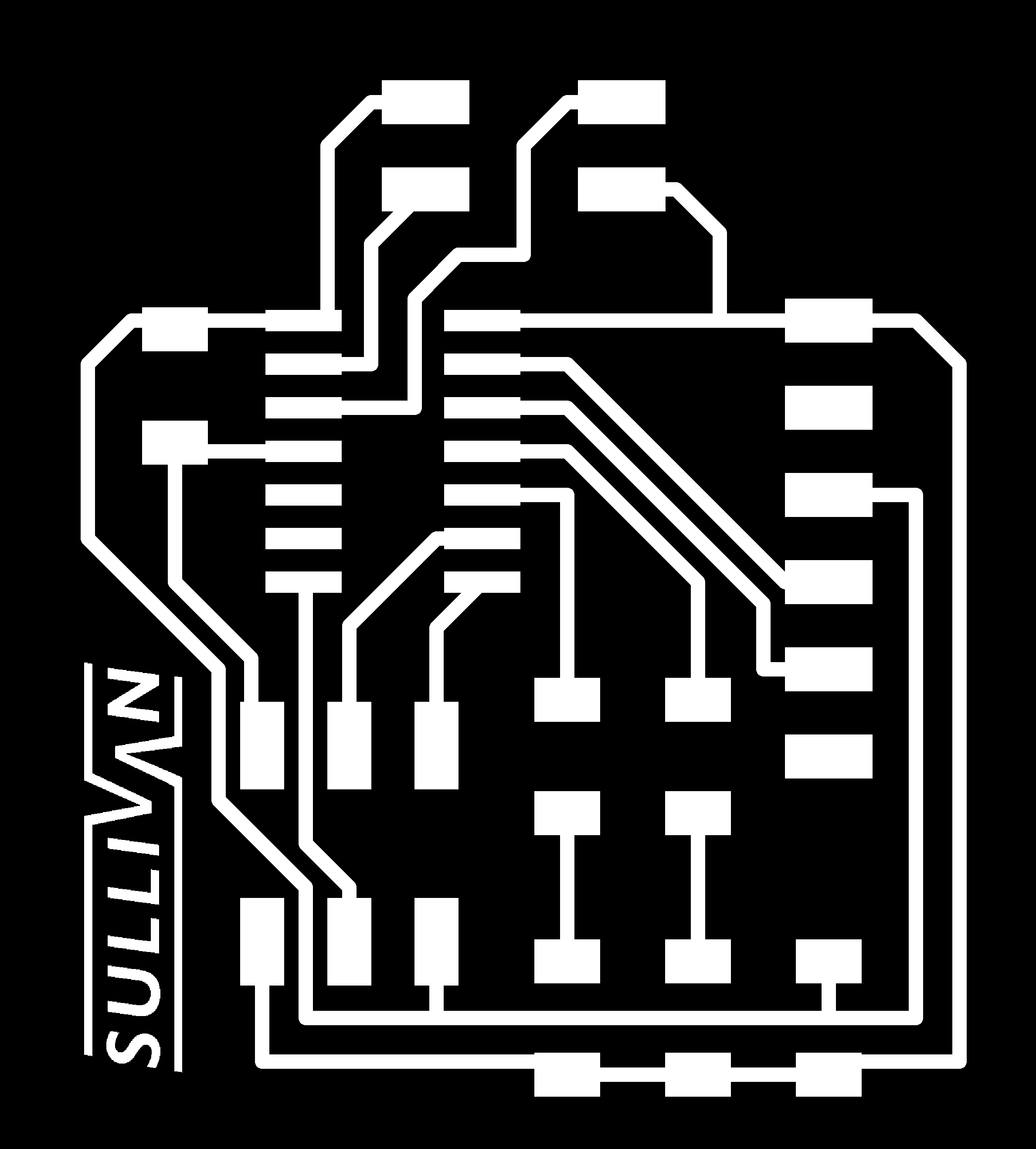
-
Successful Second Design

-

-
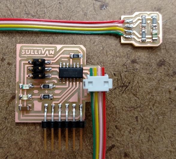
Sensor with Thermistor

-

The Sensor
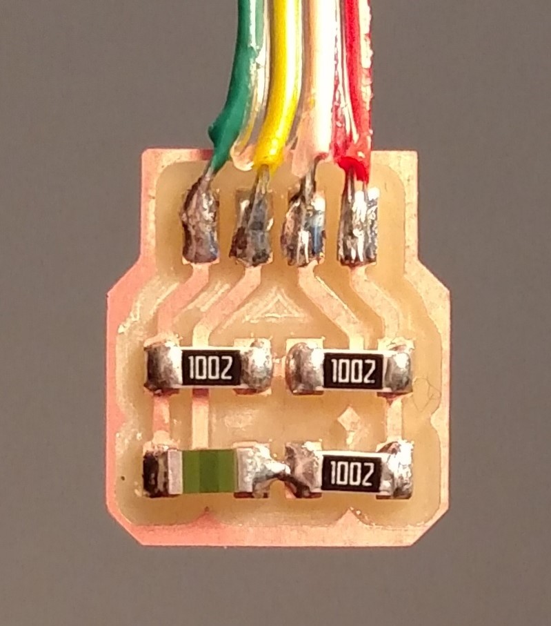
To make the sensor board I took the wheatstone bridge with the NTC
from
Neil's Board
and just moved it to a separate board. Then I added four pads so
that I could solder a cable directly to the circuit.
The four pads in the image correspond to ground (green), pin 6
(yellow), pin 10 (pink), and VCC (red). In the bottom left is the
thermistor which is in a wheatstone bridge consisting of the three
10k ohm resistors.
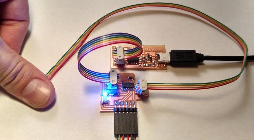
The other end of the cable connects to the ATtiny board using a 2x2
header.
Failed First Try
As I said before, I had just finished milling and stuffing the first
board before realizing I used the wrong pins. The image to the left
shows the completed first board and the attached sensor board. This
design has a red and blue LED meant to indicate different
temperatures.
It wasn't a total waste of time since I milled and stuffed the
little sensor board at the same time. Since I designed the sensor as
an external board then it could still be used.
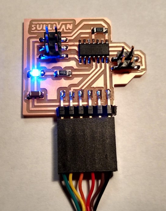
Successful Second Try

The board to the right is the successful second design. You can see
that I removed the red LED since it would have required a
significant amount of redesigning to incorporate it into my new
board.
I also rotated the 2x2 header so that the sensor cable would point
in a better direction.
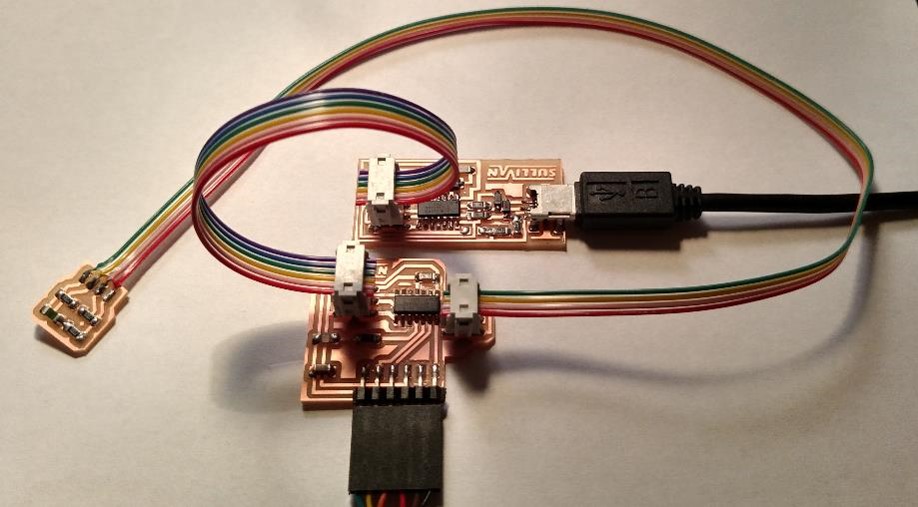
Despite messing up the pins on the first board, programming went very
smoothly for all three boards.
Programming
I decided to program the board with Arduino since this week I was a
bit short on time, especially after having to redsign my orginial
board.
Everything went much smoother than the embedded programming
week, since I had all the correct drivers and hardware.
Since I ran short on time, all that I got the board to do was
activate the blue LED when it warmed up to around body temperature.
I set the analog voltage so that the heat from my finger is just
enough to activate the LED (an analog value of about 450).
The picture on the left shows the state of the LED when the sensor
cable is detached. Since the analog input pins on the
microcontroller aren't receiving any voltage then the output is a
high state for the LED.
Cold Thermistor
Warm Thermistor
Mistakes I Made
By far the biggest mistake I made was connecting the NTC to the
digital pins on the ATtiny44. I should have been much more careful
about which pins I chose and it ended up adding several hours to my
project for the week.
I also didn't have enough time to really program the board well this
week so I plan on practicing with different languages in the weeks to
come.