Week 3: Electronics Production
This week's assignment was to build a PCB -- essentially an attiny ISP programmer board -- using the Modela printer at the machine shop, solder components on the board, and program the board using avrdude or similar tools. This was my first time building a PCB and soldering surface mount components, so it was a great learning experience that will help me for a long time! :)
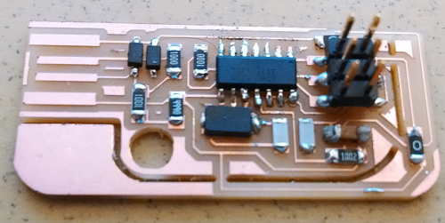
The finished board looked like the following.
Cutting and Carving the Board
On the sacrificial board, I taped the copper board and placed the drill bit of the Modela at the desired coordinates (min. x, min. y) by adjusting the values from the fab module interface.
The default parameters needed to be changed a little bit in order to avoid shorts in the board. Jonathan Bobrow helped me figure out the right parameters.
speed: 4
cut depth: 0.1
tool diameter: 0.3
For cutting the board all the way through, the following parameters were used.
speed: 4
cut thickness: 1.7
tool diameter: 0.79
Soldering
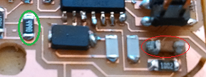
This was my first time soldering surface mount components. Putting the solder directly on top of the components would produce unnecessary blobs. On the second day of soldering, another media labber Guy Ziskind showed me some nice tricks to solder surface mount components. Applying flux to clean the surface and picking a trace amount of solder on top of the tip was enough to solder the rest of the components. The following figure shows a capacitor soldered using my previous technique (red circle), and the soldering done on the second day (green circle).
I also soldered at a few places where it seemed that the tool diameter caused too much copper to wear off.
Programming the Board
I installed avrdude on windows and tried programming the board using an exisiting and working programming board, but received error messages saying that my usb connections were not right. So I flipped the 2x3 header connections and tried it again, but this time the error message said that the device was not responding.
In another attempt, I borrowed an AVR MKII programmer from a labmate and tried programming the board again. However, the programmer showed a red blinking light this time. Some search within the manual suggested that this happens when the 2x3 headers pins are not connected properly to the board. I resoldered the pins and tried it again, but without any luck.
In the next phase of debugging, I tried to look for shorts using a multimeter, but I could not find any.
I will remake the board and keep trying to get a working programmer.
Lessons Learned
Tool diameter should be adjusted for fine grained circuits.
Instead of using a lot of solder and flux, we should simply apply some solder on the tip of the iron and be gentle with our components.
Debugging a board is hard, there's a lot for me to learn in this area!