week11.md
Week 11: Networking with ESP8266
For this week I set out to make a board that will show realtime MBTA bus arrival times using the ESP8266 wifi module and a LCD. Seemed doable. People of the internet have been excited about the ESP8266 lately. Here is a snapshot of google trends for searches for esp8266 vs couple of other arduino favorite processors.

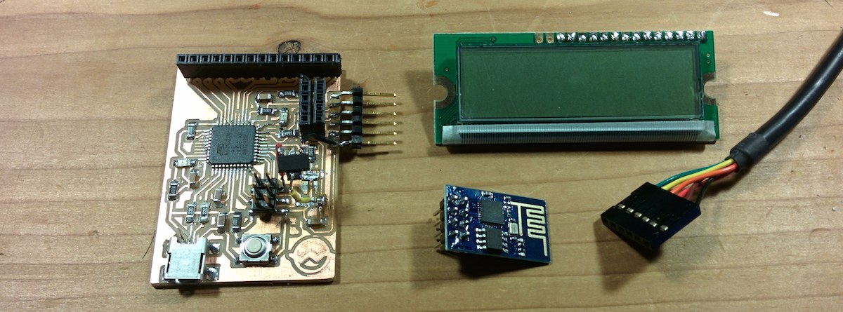
The Master Plan
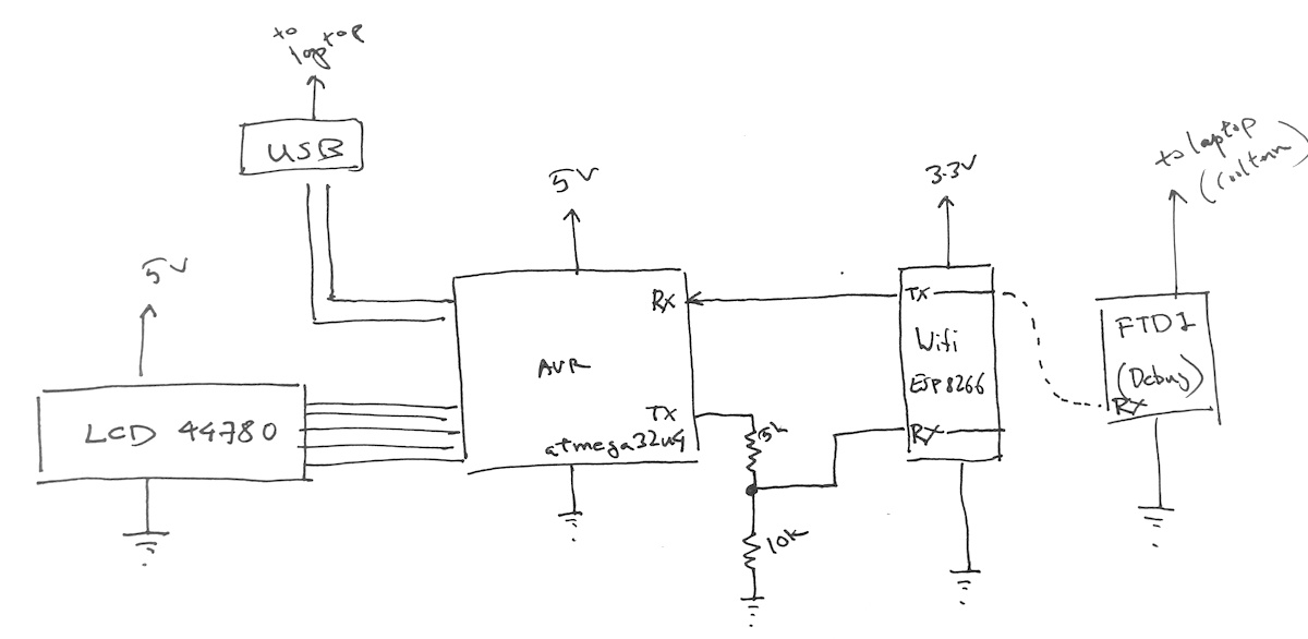
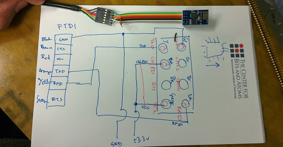
That's the rough plan. I run the atmega32u4 and the LCD at 5V. The ESP8266 I power at 3.3V using a regulator. As for the logic chatter, I feed the 3.3V output of the ESP8266 to the atmega and I feed the output of the atmega through a voltage divider to bring it to 3.3V suitable for the ESP8266. This turned out to be a mistake that I will discover 15 hours later.
Mounting the lcd
I got a package from adafruits.com that I am modifying. First copy the package by
- opening target library
- selecting the device in the main window nav tree
- right-click copy to library
To get the mill to drill holes where needed, I am using the circle tool to draw filled cirlces (width 0).
ESP8266 package
I am making an eagle package and device for esp8266 header.
Steps:
- copy over a suitable part from another library (MA04-2 from con-lsb, a 4x2 header)
- open my library
- right click on part from source library
- click copy to library
- rename the package with
rename MA04-2.pac ESP8266_HDR_REVin the command bar - click package and select the package to edit
- get rid of all the crap that's there (outline etc)
- add circles in the milling layer
- use name tool to give names (GND, RST, GPIO2, etc.)
- added some helpful text in the document layer
- create a new symbol (ESP8266)
- use pin tool to lay down 8 pins in row
- use name tool to add the same names I used in the package step
- create new device (ESP8266) (click device, pick a new name)
- use the place tool (plug thingie) to add the newly created symbol
- click new on the lower right to add the package
- click connect and go through and connect all the pins with all the pads
Milling
Prep for milling
display none top padsto get the tracesdisplay none millingto get the milling guidesdisplay none outlineto get the outline
I separated the holes and outline to make sure the board outline doesn't get cut before the holes are drilled.
Now it looks like I am just shy of the mill diameter for the holes. I have to lie about the tool diameter again (0.75mm instead of the actual 0.79mm)
Avenue of broken dreams
Will P said it well a few years ago.
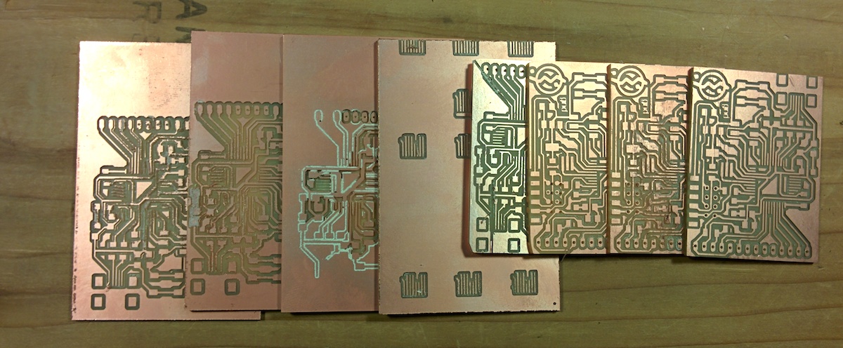
Here is why the various boards failed (from left to right)
- trace carnage
- trace carnage
- trace carnage + bad depth (maybe I pushed the end mill down too much when setting Z)
- test pattern
- my bad: bad flow control (dsrdtr instead of rtscts). modela cut a gash
- drill holes are off. this is why you drill holes first and then cut the outline
- minor trace carnage.
- good board
Traces coming off was a recurring issue for me. What I think helped fix it was slowing the speed to 3mm/s and taping the entire backside of the baord down. I think vibrations from a loosely attached board (just 3 tapes) was causing the traces to come off.
Stuffing
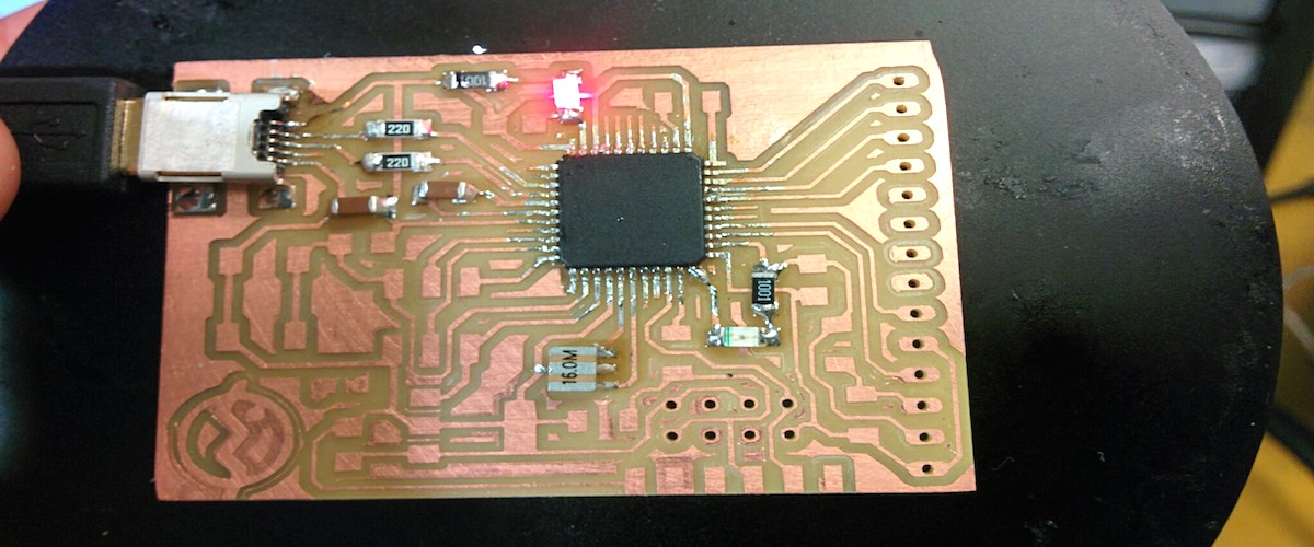
Very little is needed to get the processor to talk to USB. The crystal, the two 2ohm resistors and 2 caps are all that's needed to talk to the host. Caps are probably optional too. The other components are power LED and a LED on the txled line to run a blink test.
Using DFU
With just the minimal testing components I tried to see if I could program the chip using DFU. When I attach it to a laptop it identifies itself as a DFU usb device to the host. I can talk to it with dfu-programmer:
ubuntu:esp8266$ sudo dfu-programmer atmega32u4 get product-name
Product Name: 0x95 (149)
I looked up some instructions for programming it over DFU but couldn't quite get the bootloader to load successfully http://arduino.cc/en/Hacking/DFUProgramming8U2
ubuntu:bootloaders$ sudo dfu-programmer atmega32u4 flash caterina/Caterina-Leonardo.hex
Bootloader and code overlap.
Use --suppress-bootloader-mem to ignore
Using --suppress-bootloader-mem worked to the extent that the chip now identified itself as Arduino Leonardo but I couldn't upload
sketches to it. Maybe it wasn't the bootloader but just code that ran after the atmel dfu bootloader.
Anyway, I decided to move on.
http://www.instructables.com/id/ESP8266-Wifi-Temperature-Logger/step2/ESP8266-Setup/ http://hackaday.com/tag/esp8266/ http://zeflo.com/2014/esp8266-weather-display/
Testing ESP8266
I tested the esp8266 using FTDI cable to get a feel for the AT scripting language. Here is a sample chat session
AT+RST

OK
<line noise>
[Vendor:www.ai-thinker.com Version:0.9.2.4]

ready
AT+CWLAP

+CWLAP:(0,"xfinitywifi",-63,"e6:3e:fc:7c:0b:00",1)
+CWLAP:(4,"californiadreaming",-82,"58:23:8c:3e:7b:65",1)
+CWLAP:(0,"xfinitywifi",-84,"5a:23:8c:3e:7b:67",1)
+CWLAP:(4,"JorgesCrib",-60,"c0:c1:c0:e8:28:83",1)
+CWLAP:(4,"HOME-98B0",-56,"cc:03:fa:3a:98:b0",1)
+CWLAP:(0,"xfinitywifi",-58,"ce:03:fa:3a:98:b2",1)
+CWLAP:(0,"xfinitywifi",-82,"ce:03:fa:82:e4:3e",1)
+CWLAP:(4,"maulmane",-64,"e8:3e:fc:7c:0b:00",1)
+CWLAP:(0,"xfinitywifi",-87,"ce:03:fa:83:d4:ce",1)

AT+CWJAP?

ERROR
AT+CWJAP="trouble","xxx"

OK
AT+CWJAP?

+CWJAP:"trouble"

OK
AT+CIPMUX=1

OK
AT+CIPSTART=4,"TCP","77.92.69.132",80

OK
Linked
AVR <-> ESP8266
I had a hard time initially getting avr to talk to the esp8266. None of the libraries worked. By hooking up the FTDI cable's RX to the module's TX or avr's TX I could listen in on the conversation which really helped the debugging process. Long story short, if there is a delay between Serial1.begin() and Serial1.println() the command doesn't go through. However, if the print occurs soon after Serial.begin() it's fine.
here is a simple example that does not print the second AT:
void setup() {
  // put your setup code here, to run once:
  Serial1.begin(9600);
  Serial1.println("AT");
  delay(100);
  Serial1.println("AT"); // doesn't get transmitted
}
here is the output from the module's TX line from the FTDI's point of view
AT

OK
However, lot of chatter on the line is fine.
void setup() {
  Serial1.begin(9600);
  for (int i =100; i > 0; i--) {
      Serial1.print(i);
      Serial1.println(" bottles of beer on the wall");
      Serial1.print(i);
      Serial1.println(" bottles of beer");
      Serial1.println("take one down and pass it around");
  }
}
around 71 bottles of beer the message gets garbled with the wifi module on board and then stops shortly after. without the wifi module transmission is fine.
...
ERROR
73 bottles of beer on the wall

wrong syntax

ERROR
73 bottles of beer
take one down and pass it around

<line noise>
[Vendor:www.ai-thinker.com Version:0.9.2.4]
Short delays with transmission is fine.
void setup() {
  // put your setup code here, to run once:
  Serial1.begin(9600);
  Serial1.println("99 bottles of beer on the wall");
  Serial1.println("99 bottles of beer");
  Serial1.println("take one down and pass it around");
  for(int i =0; i < 10; i++) {
    delay(10);
    Serial.print(i);
    Serial1.println(" hello polly");
  }
  Serial1.println("AT");

}
output from esp8266
99 bottles of beer on the w<line noise>polly

wrong syntax

ERROR
 hello polly

wrong syntax

ERROR
 hello polly

wrong syntax

ERROR
 hello polly

wrong syntax

ERROR
 hello polly

wrong syntax

ERROR
 hello polly

wrong syntax

ERROR
 hello polly

wrong syntax

ERROR
AT

OK
I thought maybe all that's needed is a keep-alive on the line:
void setup() {
  // put your setup code here, to run once:
  Serial1.begin(9600);
  Serial1.println("99 bottles of beer on the wall");
  Serial1.println("99 bottles of beer");
  Serial1.println("take one down and pass it around");
  for(int i =0; i < 10; i++) {
    delay(10);
    Serial1.println(" ");
  }
  Serial1.println("AT");

}
but it doesn't seem to work:
output from module
99 bottles of beer on the wall

wrong syntax

ERROR
99 bottles of beer

wrong syntax

ERROR
take one down and pass it around

wrong syntax

ERROR
no AT.
now it has come to this that even a single delay right after initializing the serial line prevents the line from being used.
void setup() {
Serial1.begin(9600);
delay(100);
Serial1.println("AT"); // doesn't go out on the line
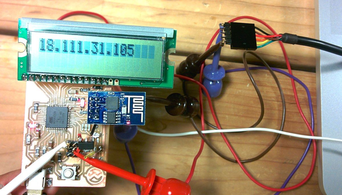
In the end I started to suspect the voltage divider because of Neil's remark that the values might be too high. So I bypassed it and hooked up the RX, TX of the module to MOSI and MISO of the avr using wire clips. Then it all worked as expected.
#include <SoftwareSerial.h>
#include <LiquidCrystal.h>
/*
 * LCD initialization
 * RS - 4
 * E - 12
 * D4 - 9
 * D5-  10
 * D6 - 5
 * D7 - 13
 */
// initialize the library with the numbers of the interface pins
LiquidCrystal lcd(4, 12, 9, 10, 5, 13);

void lcd_print(const char *c) {
  lcd.setCursor(0,0);
  lcd.print(c);
}

SoftwareSerial wifi(14, 16); // RX, TX, (14-MISO, 16-MOSI)

void setup() {
  lcd_print("in setup");
  wifi.begin(9600);
  wifi.setTimeout(15000);
  delay(1000);
  while(wifi.available()) wifi.read();

  wifi.println("AT");
  if(wifi.find("OK")) {
    lcd_print("got ok");
    TXLED1;
  }
  while(wifi.available()) wifi.read();

  delay(100);
  TXLED0;
  delay(1000);
  wifi.println("AT+RST");
  if(wifi.find("ready")) {
    lcd_print("reset succeeded");
    TXLED1;
  }
  TXLED0;
  while(wifi.available()) {
    wifi.read();
    delay(1);
  }

  delay(1000);
  wifi.println("AT+CWJAP=\"MIT\",\"\"");
  if(wifi.find("OK")) {
    lcd_print("joined MIT");
    TXLED1;
  }

  lcd_print("                    ");
  delay(1000);
  char ip_buf[100];
  wifi.println("AT+CIFSR");
  wifi.readBytesUntil('\n', ip_buf, 100);
  wifi.readBytesUntil('\n', ip_buf, 100);
  int n = wifi.readBytesUntil('\n', ip_buf, 100);
  ip_buf[n-1] = 0;
  lcd_print(ip_buf);

}
Required some ugly clips to connect the pins (and to the FTDI cable) but hey, IP:
Arduino command line interface
As an aside, arduino > 1.5.0 has a command line interface:
- compile:
arduino --board arduino:avr:leonardo --verify sketch.ino - compile & upload:
arduino --board arduino:avr:leonardo --upload sketch.ino --port /dev/ttyACM? --verbose