Week 5: Circuit Design
We had to design a hello world board (blink LED). The main goal is to learn to do circuit layout. I used Eagle although KiCAD was tempting.
In a break from previous weeks, instead of writing a journal, I will create checklists as I am going along. Will be easier for you
Schematic
- First draw on paper
- Use standard/LED library to get LED
- Use standard/supply1.lbr library to get VCC, GND
- Rest of the part from fab.lbr
- Use named nets for readability
- keep conceptually separate circuits separate in the schematic (eg. don't wire switch and led circuit together) (from Jeff D)
Board Layout

- Drawing traces should be newspaper puzzles.
- Rotating a component in Eagle is not obvious. Click to select and then right click. (right click without selecting opens a context menu)
- First lay everything out with a lot of space and then shrink
- protip: to check if you are done, hit ratsnest to see if there are any airwires left
- Avoid right angle traces (from Jeff D). Can reflect high frequency signal. Also bad mechanically.
Exporting
- Redraw the dimension layer using wire so it snug around the board
- Drag the fainter gray outline (board dimension) so it it is close to the dimension outline
- In the command bar:
display none topshows only the traces display top tNames dimension tPlace tDocugives traces, name, outline and placement + component outline- Use
display none topand then export PNG with 600 dpi for traces display none dimensionand then export PNG with 600 dpi for outline cut- Use gimp to invert and fill out the outline cut image so it is white on the outside all the way to the edge and black in the middle
- You can also use gimp for adding some flare to the image. I just added round corners because.
Milling

On Roland Modela
- put in view mode
- tape down FR1 board on top of sacrificial layer
- change end mill to 1/64 for traces 1/32 for outline
- unscrew two screws on the shank
- chnage mill
- zero end mill
- use move to xmin, ymin to get to a corner of the board
- lower end mill with up / down button on modela until it is close to the board
- unscrew end mill
- hold end mill in hand and lower head a bit more (shank will spin while you hold end mill)
- lower end mill by hand and it touches the board
- hold it down while you screw the two screws back in
- this is now 0 Z
On the computer
- make sure mod_server is running
- make sure settings for talking to modela is correct (on modela-1 ttyS0 9600 rts cts)
- calculate path
- verify path by inspection
- hit send
Stuffing

- Start from inside out
- Start from the shortest component
- Use a blob of solder to hold component in place
- Solder other ends of component
- Resolder the holding end
Things that went wrong (tm)

- After I milled a board I found out that the bit must have been dull. produced a board with furry traces
- Fab modules errored out with WebGL not supported. As a work around, I used a different computer to compute the tool path and then copied over the rml file and ran mod_serial.py from command line to push the path to the tool. Advice from mike: clear cache

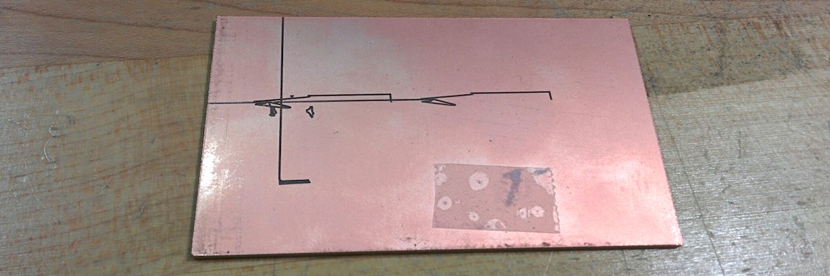
- The flow control for the serial communication to the mill wasn't set correctly (rtscts) which sometimes caused the millhead to wander off and kill the board
- Picked the wrong registers for soldering. cf register codes