Week 7: Embedded Programming
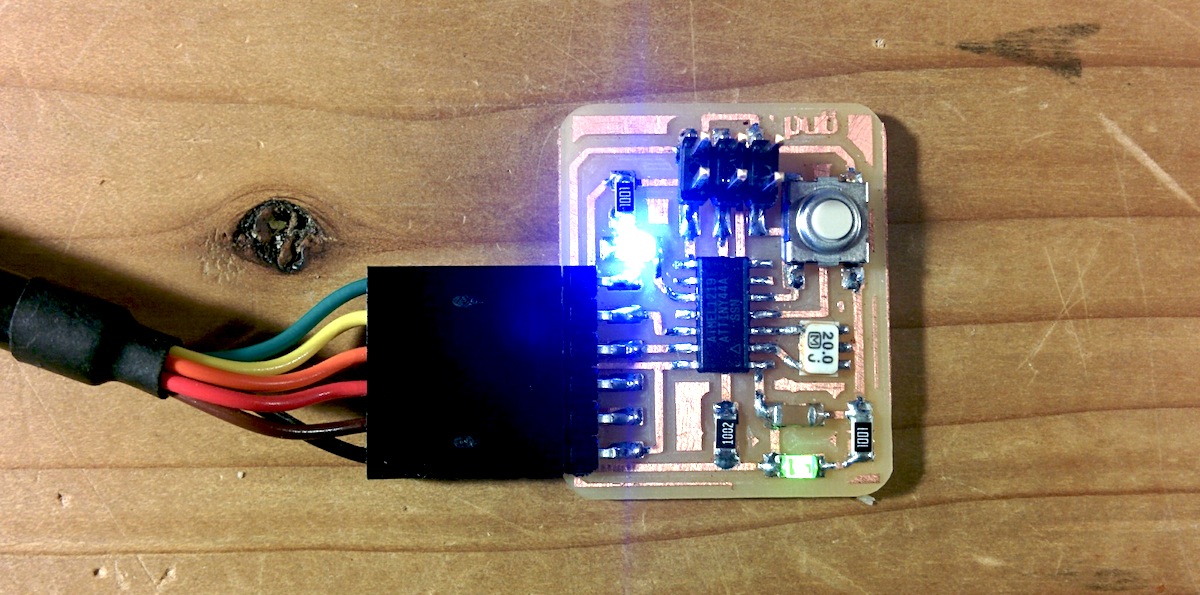
We have to program our hello ftdi board from week 5 to blink a LED using a switch. This part was relatively easy for me as I had done AVR programming before.
Here is what lsusb shows with the FTDI cable plugged into my board and the ISP mkII programmer plugged in.
usb shows ftdi cable and the programmer:
ubuntu$ lsusb
Bus 001 Device 004: ID 203a:fff9
Bus 001 Device 003: ID 203a:fff9
Bus 002 Device 002: ID 0403:6001 Future Technology Devices International, Ltd FT232 USB-Serial (UART) IC
Bus 002 Device 006: ID 203a:fffe
Bus 001 Device 001: ID 1d6b:0002 Linux Foundation 2.0 root hub
Bus 002 Device 001: ID 1d6b:0001 Linux Foundation 1.1 root hub
Bus 003 Device 001: ID 1d6b:0002 Linux Foundation 2.0 root hub
Bus 004 Device 001: ID 1d6b:0003 Linux Foundation 3.0 root hub
Bus 002 Device 007: ID 03eb:2104 Atmel Corp. AVR ISP mkII
I started off by compiling and downloading Neil's echo program:
ubuntu$ sudo avrdude -p t44 -P usb -c avrisp2 -U flash:w:hello.ftdi.44.echo.c.hex

avrdude: AVR device initialized and ready to accept instructions

Reading | ################################################## | 100% 0.01s

avrdude: Device signature = 0x1e9207
avrdude: NOTE: FLASH memory has been specified, an erase cycle will be performed
         To disable this feature, specify the -D option.
avrdude: erasing chip
avrdude: reading input file "hello.ftdi.44.echo.c.hex"
avrdude: input file hello.ftdi.44.echo.c.hex auto detected as Intel Hex
avrdude: writing flash (776 bytes):

Writing | ################################################## | 100% 1.53s

avrdude: 776 bytes of flash written
avrdude: verifying flash memory against hello.ftdi.44.echo.c.hex:
avrdude: load data flash data from input file hello.ftdi.44.echo.c.hex:
avrdude: input file hello.ftdi.44.echo.c.hex auto detected as Intel Hex
avrdude: input file hello.ftdi.44.echo.c.hex contains 776 bytes
avrdude: reading on-chip flash data:

Reading | ################################################## | 100% 1.45s

avrdude: verifying ...
avrdude: 776 bytes of flash verified

avrdude: safemode: Fuses OK

avrdude done.  Thank you.
I modified it to add the LED output control using interrupts. The I/O section attiny44 datasheet tells me how to configure the ports for my pins. Here are my changes to the echo.c code.
Some definitions at the top of the file:
#define LED_PORT PORTA
#define LED_DIRECTION DDRA
#define LED_PIN (1 << PA3)
#define SWITCH_PORT PORTB
#define SWITCH_DIRECTION DDRB
#define SWITCH_PIN (1 << PB2)
Initilization before the main loop:
int main(void) {
   ...

   //
   // initialize output pins
   //
   set(serial_port, serial_pin_out);
   output(serial_direction, serial_pin_out);
   set(LED_PORT, LED_PIN);
   output(LED_DIRECTION, LED_PIN);

   clear(SWITCH_DIRECTION , SWITCH_PIN); // set for input (should be default)
   set(SWITCH_PORT, SWITCH_PIN);         // enable pullup

   // enable INT0 interrupt
   GIMSK = 1 << INT0;                    // enable int0 and disable pcie

   set(MCUCR, 1 << ISC01);               // trigger on falling edge
   clear(MCUCR, 1 << ISC00);

   sei();

   //
   // main loop
   //
   ...
And the tiny interrupt service routine.
ISR(INT0_vect) {
      set(LED_PORT, LED_PIN);
      _delay_ms(250);
      clear(LED_PORT, LED_PIN);
}
There is no switch debouncing so sometimes I get a few LED blinks for one press. That said, it worked and I was done.
Arduino
I hadn't used Arduino before so I wanted to give it a shot. This is mostly to get at the libraries written for arduino and the community support. The libraries mostly target atmega328p which is more full featured than the tiny we have been using.
"First things first". I need to get a atmega328p arduino board. I used Neil's hello.328p to mill out a board. Soldering the atmega328p, which came in a TQFP-32, was tricky. I first tried with tinning all the copper and the leads and then trying to reflow the chip down on to the board using the iron. This didn't work very well. The legs floated above the copper traces and took a lot of solder to get it covered. btw, protip on the solder wick: fluxing the copper braid helps in soaking up solder.
Well, shit. I had failed to notice that a trace was missing from the milling process. To make matters worse I tried to bend the pin of the IC up with a wire jumper in mind and then broke the pin. This was connected to the RX pin for the FTDI so I wouldn't be able to use serial programming or communication without the pin.
New board. Took 2 more tries with the mill to get a new board out. The first milling also took the fine traces out. Might have been a problem with the end-mill being dull. For the soldering the atmega328p
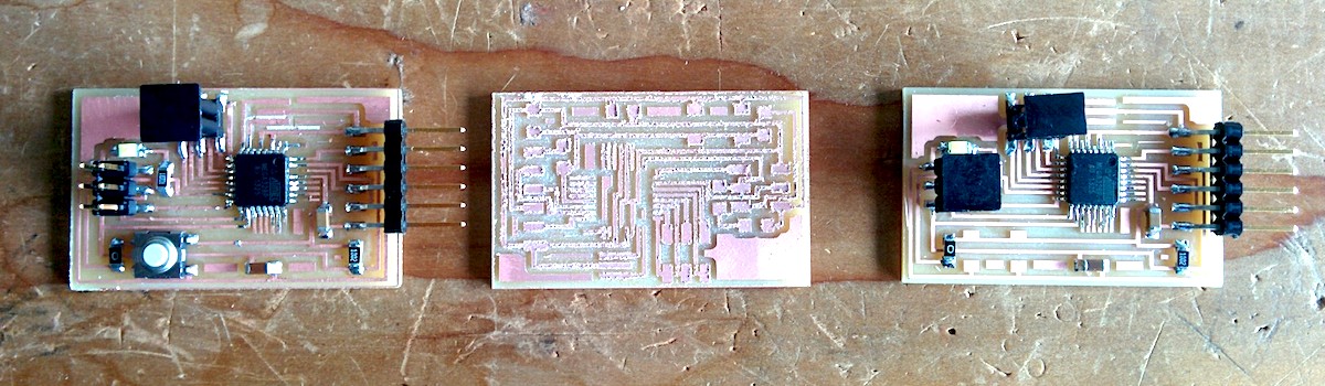
New board works. All I had to do was to modify the boards.txt file in the arduino environment. Neil's supplied board.txt had some minor hiccups presumbably because I was using a new version of arduino.
Here is what I added to arduino-1.5.8/hardware/arduino/avr/boards.txt
################################# Fab board ###############

hello.name=hello.arduino, ATmega328P, 5V, 8MHz internal oscillator
hello.upload.protocol=arduino
hello.upload.maximum_size=30720
hello.upload.speed=57600
hello.upload.tool=avrdude
hello.bootloader.tool=avrdude
hello.bootloader.low_fuses=0xE2
hello.bootloader.high_fuses=0xDA
hello.bootloader.extended_fuses=0x07
hello.bootloader.path=arduino:atmega
hello.bootloader.file=atmega/ATmegaBOOT_168_atmega328_pro_8MHz.hex
hello.bootloader.unlock_bits=0x3F
hello.bootloader.lock_bits=0x0F
hello.build.mcu=atmega328p
hello.build.f_cpu=8000000L
hello.build.core=arduino:arduino
hello.build.variant=arduino:standard