Week 9: Step Response Input with Big Iron
For this week I wanted to experiment with step response sensors but also wanted to get started on designing a board with a larger processor. In particular the atmega32u4 looks interesting because it has all the capabilities I would want for my final project and has a built-in USB controller so I can cut the FTDI chord. It doesn't play to a miminimalism aesthetic though which is a pity and is a more expensive part.
Designing a minimal 32u4 board
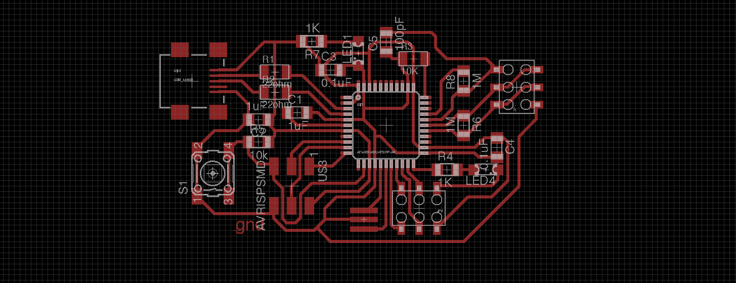
I ended up designing two boards. First a basic one with just the pins brought out to headers. To design the board, I looked at the schematics of the Arduino Micro and the Teensy 2.0. The [AVR application notes][avr042] was also a good bedtime read. Here is what I ended up with
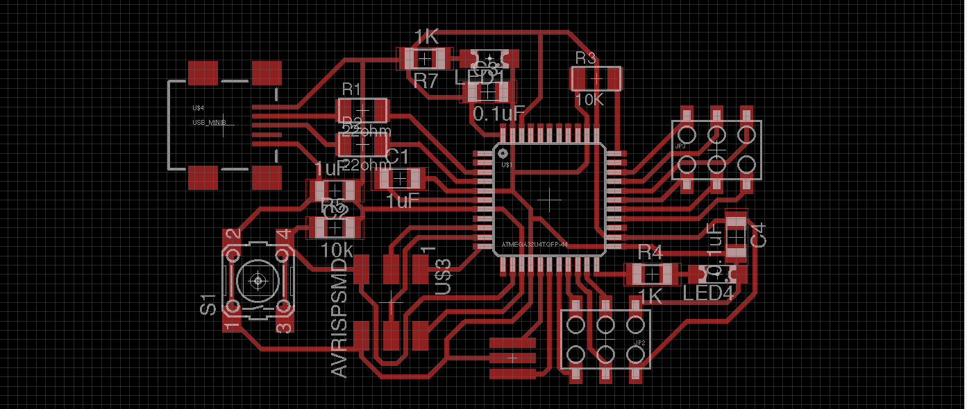
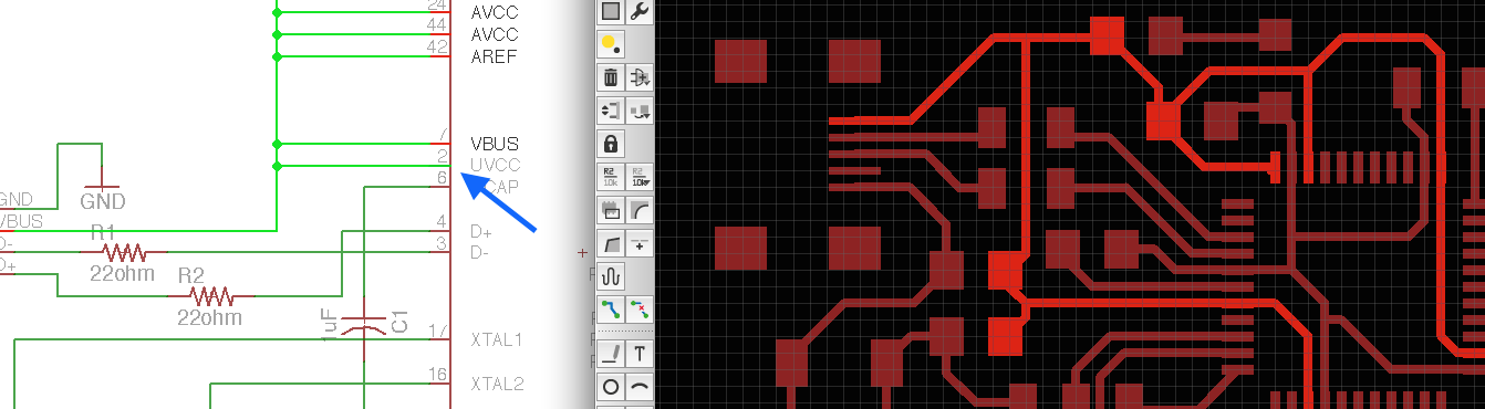
The bits marked in green are the only required components. The rest which consists of status LEDs and bypass caps and a pull down resistors on HWB, pull up on RESET are nice to have. I also think that ISP can be ditched as well since the chip is supposedly factory shipped with a bootloader. There is a bug in the design that I found out only much later.
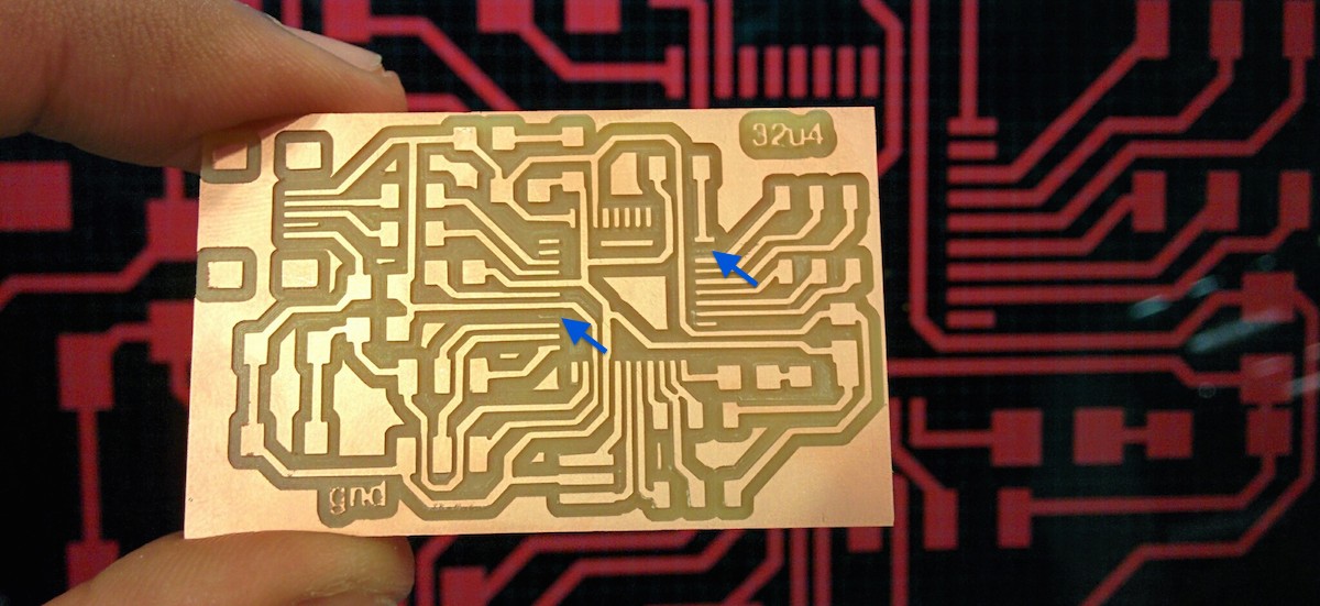
Unfortunately, Straight up exporting didn't work well with path planning. SparkFun's board footprint for the atmega32u4 didn't leave enough clearance between the pins so I would have to set the tool diameter to 0.25mm to convince the tool head to go between pins. While this would cut the part, everything on the board would shrink as the path planning tool wouldn't offset the head enough for the thicker head.
To get around this, I opened the image up in gimp and then selecting the areas around the chip pin, I used an 'Erode' filter to increase clearance. Kind of hacky if you ask me. I need to find out how to redraw the library part. Still needing to set the tool head to 0.33mm
Changing package for atmega32u4
The standard SparkFun package has too fat pads
- In Eagle open up fab library. (will pop open new window)
- In the library nav tree of the main window, choose the atmega32u4 device and click copy to library
- Now fab has a copy of the 32u4
- Delete all the packages we don't want (QFN crap)
- Choose TQFP44 in the package list
- Change the pad size by typing 'change smd' into command line
- Select 0.06 x 0.015 (I made this up)
- Click on pads to change them to new size
- In schematic click replace to replace the sparkfun part with our new part.
I can't believe that worked and didn't mess up my layout. Now I am back to cutting with a 0.33mm tool head but at least I don't have to go through gimp
Milling
I struck out a few times milling the boards:
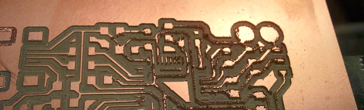
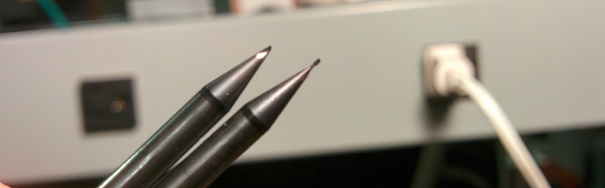
due to a broken end mill. Perhaps it broke while I was milling:
even when the board got milled reasonably well (with tool set to 0.33mm for 0.4mm tool), any unattached pad would go MIA:
Stuffing
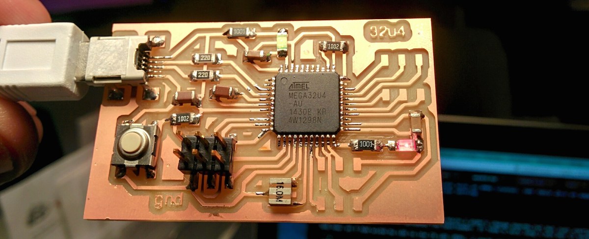
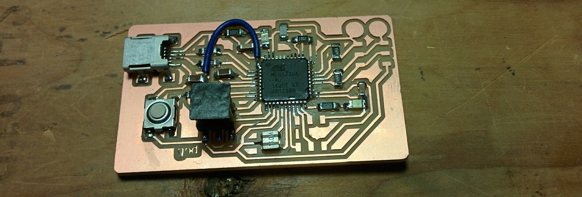
The only trick to stuffing was setting the uc correctly on the pads. I first put a dab of solder on one pad, carefully put the uc so that all the pins are correctly lined up, hold it down with my finger and then reflow the solder. Do it for the kitty corner pad. Then flux the pins and pads and put globs of solder on all the pins and suck it out with the braid.
Testing with avrdude
Found a neat trick. avrdude without any -U flag provides quick testing:
ubuntu:arduino$ sudo avrdude -p m32u4 -c avrisp2 -P usb

avrdude: AVR device initialized and ready to accept instructions

Reading | ################################################## | 100% 0.01s

avrdude: Device signature = 0x1e9587

avrdude: safemode: Fuses OK

avrdude done.  Thank you.
this means that the board is able to talk ISP. chip is alive!
Fuses
you can read fuse values with avrdude using this:
ubuntu:arduino$ sudo avrdude -p m32u4 -c avrisp2 -P usb -U hfuse:r:hfuse.hex:h

avrdude: AVR device initialized and ready to accept instructions

Reading | ################################################## | 100% 0.01s

avrdude: Device signature = 0x1e9587
avrdude: reading hfuse memory:

Reading | ################################################## | 100% 0.00s

avrdude: writing output file "hfuse.hex"

avrdude: safemode: Fuses OK

avrdude done.  Thank you.
Mine are set to
- lfuse: 0x5E
- hfuse: 0x99
- efuse: 0xF3
Which says that it should an external clock > 8Mhz?
According to Engbedded's fusecalc, I have CKSEL0 set but CKSEL1..3 is 0. According to the datasheet CKSEL[3:0] = 0001 is reserved. Nope. It's the opposite. Note that engbedded flips the display of 1s and 0s. My CKSEL[3:0] is set to 1110
from the datasheet (section 6.2.1):
The device is shipped with Low Power Crystal Oscillator (8.0 - 16MHz) enabled and with the fuse CKDIV8 programmed, resulting in 1.0MHz system clock with an 8MHz crystal. See Table 28-5 on page 331 for an overview of the default Clock Selection Fuse setting.
Using Arduino
Since the board closely follows an arduino micro I didn't change boards.txt but just configured the arduino IDE to use micro and uploaded the bootloader. It took a very long 1 min but it worked.
And now, as I had wired my LED to the TX LED (PD5), I could use the builtin macro to turn the LED on and off:
void loop() {
    TXLED1; // turn tx led on
    delay(1000);
    TXLED0; // off
    delay(1000);
}
for the record, TXLED* is defined in variants/micro/pins_arduino.h:
#define TXLED0                  PORTD &= ~(1<<5)
#define TXLED1                  PORTD |= (1<<5)
#define RXLED0                  PORTB &= ~(1<<0)
#define RXLED1                  PORTB |= (1<<0)
#define TX_RX_LED_INIT  DDRD |= (1<<5), DDRB |= (1<<0), TXLED0, RXLED0
Udev rules for ISP
avrdude and arduino ide complains writing to usb if they are not running as root. I don't like blanket sudo access so I added the following udev rule in /etc/udev/rules.d/avrisp-usb.rules
SUBSYSTEM!="usb_device", ACTION!="add", GOTO="avrisp_end"

# Atmel Corp.JTAG ICE mkII
ATTR{idVendor}=="03eb", ATTR{idProduct}=="2103", MODE="660", GROUP="plugdev"

# Atmel Corp. AVRISP mkII
ATTR{idVendor}=="03eb", ATTR{idProduct}=="2104", MODE="660", GROUP="plugdev"

# Atmel Corp. Dragon
ATTR{idVendor}=="03eb", ATTR{idProduct}=="2107", MODE="660", GROUP="plugdev"

LABEL="avrisp_end"
also adding myself to dialout:
ubuntu:dev$ groups palash
palash : palash adm cdrom sudo dip plugdev lpadmin sambashare
ubuntu:dev$ sudo usermod -a -G dialout palash
ubuntu:dev$ groups palash
palash : palash adm dialout cdrom sudo dip plugdev lpadmin sambashare
USB woes
Unfortunately the board refuses to talk USB. Based on this [arduino thread][http://forum.arduino.cc/index.php?topic=165412.0] I checked my UCAP voltage. It should have been 3.3V but is only 0V. Maybe there is a fuse to enable or disable the internal 3.3V regulator? The arduino boards have external regulators so they don't need the internal one. Hmm..
Looking at the spreadsheet it turns out that UVCC needs to be powered to supply power to the regulator for UCAP. Well shit.
Here is what the board should have been:
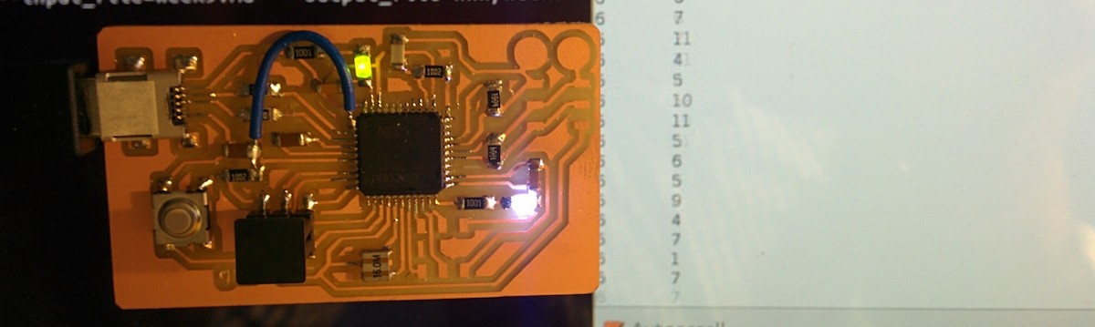
In the meantime, I jumpered it.
Reading step response sensor
Now with USB working, I could use Arduino to talk serial directly to the computer. I used arduino CapacitiveSensor library to read the capacitance of the touch pads.
Here it is sending a stream of data back.
Useful Links
- Changing package size in Eagle
- AVR042 application notes for wiring up RESET, ISP, XTAL and power
- ATmega32U4 datasheet
- Arduino micro schematic: This is what I was targetting
- AVR fuse calculator
- Teensy schematic: Used to figure out minimal 32u4 board