|
|
MAS.863 How To Make (Almost) Anything
– Fall 2014 Richard Li Output Devices Week 10 The fun of this week comes of integrating sensors with a useful
output in order for the microcontroller to physically act and respond to the inputs.
It just so happened that one of my friends in D-Lab Dan Sweeney is interested
in building a smart solar dryer system for charcoal briquettes in order to
dry them quickly and keep them ready for efficient burns within households.
For those that don’t know, the charcoal project at D-Lab is one of the
original projects that has really expanded and been implemented in many
different developing communities. By converting biomass or agricultural waste
into charcoal briquettes, value is added in making a portable on-demand and
clean cooking fuel which can help combat health problems such as indoor air
pollution, and promote income generation in a community while drastically
decreasing cost of fuels. However, a key requirement to accelerate the drying
process/enable very efficient burn is to limit moisture absorption inside the
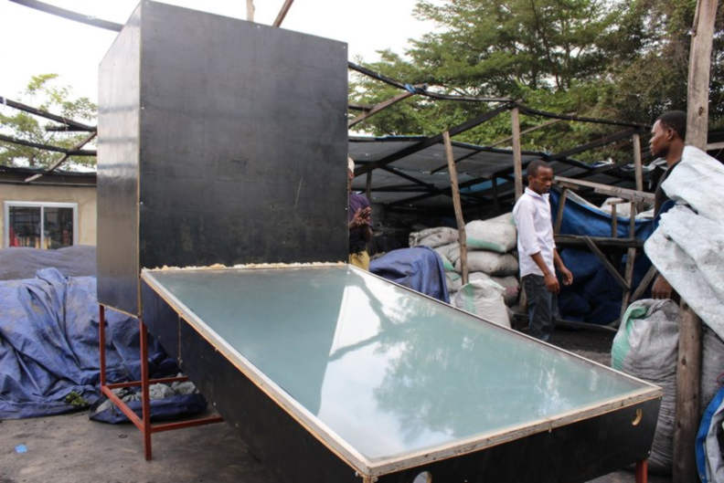
briquettes. Thus, there is an interest in building a smart solar dryer
chamber that automatically adjusts the chamber conditions to promote rapid
drying/desorption. The traditional way of drying waste-derived charcoal are
shown here:
Smart
Solar Dryer Concept This is a really ambitious project for a week, but I was motivated by
the idea that this might turn into a prototype of something that may be
actually used in the field. I should recognize the help of my roommate Sasha Siy and TA Matt Edwards for their patience in guiding me
through this particular board design process. The heavy lifting was the board
design – which ended up being a monstrous board and task compared to
ones that have been designed and fabricated thus far. Here’s the rough idea:
Charcoal is loaded into a dryer container, which is supplied with hot air
from a solar thermal inlet chamber as shown here:
To ensure that there is better drying of the charcoal briquettes (or
even other biomass that needs drying), a system is needed that will read the
humidity and the temperature of the drying chamber, and adjust air flow into
the system accordingly. Thus, the desired inputs and outputs are listed below Inputs: Humidity Sensor Temperature Sensor Outputs: Fan 1 Fan 2 LCD Screen showing the system status Additional Capabilities and tweaks: Temperature setpoint adjust knob Humidity setpoint adjust knob Fan 1 speed adjust knob Fan 2 speed adjust knob After some discussion with Dan and recommendations from others who
have used humidity sensors, it was decided that the humidity and temperature
sensors would be the DT11 (RHT03) combined humidity and temperature sensor: http://dlnmh9ip6v2uc.cloudfront.net/datasheets/Sensors/Weather/RHT03.pdf This has the advantage of bundling both into one single sensor that
is already precalibrated rather than having to make
my own. As for outputs, the key power source really is only a car lead acid
battery that is more easily accessible in Tanzanian communities. Therefore,
the fan must be powered off a 12V car battery. For the proof of concept
prototype, Dan wanted to use a 12V computer fan or a cooling fan. This was
ultimately bought: http://www.amazon.com/Antec-Big-Boy-200-Computer/dp/B000V6FKGM The question remained, how do we do the speed control and the setpoint adjustment? By reading the datasheet on the
sensor, it was found that it’s not an analog in, so a manual knob connected
in series to the sensor is not enough to change the voltage coming in, and
thus the setpoint. Since it’s a digital in read, a
potentiometer could be placed on an analog in pin of the microcontroller and
then programmed to adjust the temperature and humidity setpoint
that way. As for the speed control, while one easy way to do it is to connect
a potentiometer again in series with the fans, that would result in large
power losses and heat build up. Thus pulsed width modulation (PWM) is a
better and more energy efficient technique that can be used to control fan
speed, which can be a function of an analog in voltage on another pin
connected to a potentiometer – similar to that described for the
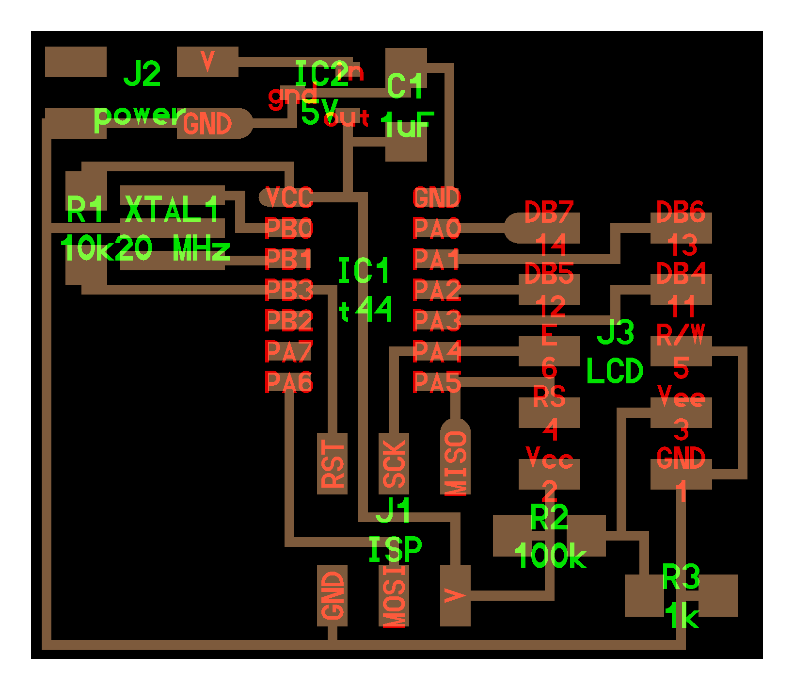
temperature and humidity control setpoints. Designing the Board This board is a large combination of temperature/humidity sensing
input boards, as well as LCD output and motor control board. Thus, a lot of
the wiring required consultation on Neil Gershenfeld’s
past examples of the LCD control board as well as the fabduino,
which utilizes the Atmega168/328 and needed in order to support the number of
pins we’ll need. http://academy.cba.mit.edu/classes/output_devices/LCD/hello.LCD.44.png
http://academy.cba.mit.edu/classes/embedded_programming/hello.ardui
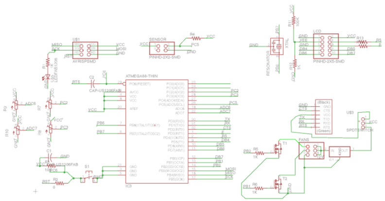
no.328P.png The schematic is shown here:
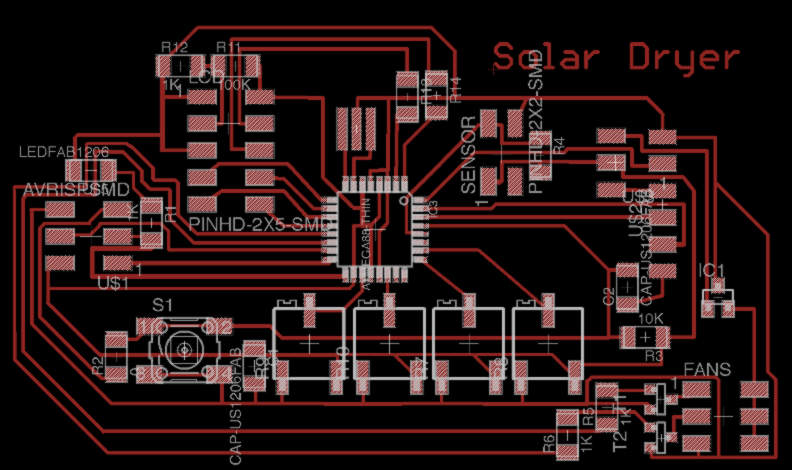
The final board layout is here:
It should be noted to arrive at such a design took a look of reviewing
of data sheets. The data sheets of the Atmega328 revealed which pins were
PWM, ADC, and simple digital pins. In the end, all the LCD screens go to
digital pins, fans/N channel MOSFETS into the PWM pins, and the
potentiometers into the ADC. Particularly for this many number of pins
utilized, the layout took a lot of trial and error and redrawing. Once again,
the design rule check was made so that the clearance
between the traces are greater than 1/64”. One important design consideration is the power source, as ultimately
this board will be run in the field and not off of a laptop/computer. Thus it
must be able to run on the car battery, and so a 5V regulator is added to the
schematic. However, during programming to the computer, and given the ftdi 5V input from the USB, it is not clear what may
happen if both the ftdi cable is providing 5 volt
while the 12V car battery is also pumping out 5V via the regulator. To
prevent any confusion, I decided to put in a SPDT switch to move between the
two modes of sourcing the MCU power from either the FTDI header, or the
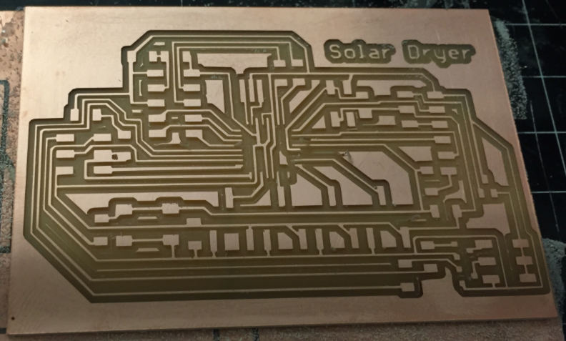
Regulator, but not both at the same time. Milling and
Stuffing the board Milling did have some issues at first, with an endmill that snapped as a result of the warped x-y
platform on which my copper board was mounted. This warping caused the endmill to dig in deeper in certain areas, and
subsequently exert large bending moments that ultimately resulted in endmill failure. This was resolved by choosing a
different position on the platform where the curvature is much less.
The first milled board did end up having leads
(particularly by the small pins of the microcontroller) lift up. Luckily, the
ones that got completely obliterated were the ones that weren’t used, while
some of the leads that were bent could be pushed back down into place and
held down rigidly once the MCU was soldered down. Particularly useful in
stuffing the board is first putting a drop of solder on one corner, lining up
the MCU pins with the pads, and then reflowing that one corner until it wicks
up onto the pin. Another trick to get each pin accurately was to rest the tip
of the soldering iron on the trace, and then feed the solder right onto the
pin/soldering iron tip interface. This causes the solder to flow and wick
onto the soldering iron and the pin. Then immediately, pull the soldering
iron orthogonally away from the pin so it “pultrudes”
the solder out and onto the trace. Note, that I ended up having to remill and restuff the board
with an atmega168 because of some issue of arduino
IDE recognizing the 328P board (mentioned in the next section). Programming
the Board Once again using the FabISP
programmer, I connected the 2X3 via ribbon cable to the 2X3 programming header
of the board. Then I connected the FTDI cable to the computer via USB and the
FTDI headers of the board (mainly to provide the 5V power). It’s important to
make sure the power source switch is moved to the FTDI source. We need to allow for Arduino
IDE to be able to recognize and setup the bootloader
for the atmega328. Well, it turns out that a previous tutorial has the
boards.txt file that allows for the setup of fabduino
using atmega168. Download this text file, copy the lines, and paste into the boards.txt
file that actually resides in your hardware subfolder under the system arduino folder of your computer. Once again, verify
you’re using the right ttyserial device, and you’ve
select USBtiny for the programmer. I then ran the
burn bootloader, and ran into an error message
indicating that it could not recognize any atmega168 device – which is
true given that my board was stuffed with the 328p. Rather than taking out
the 328p chip and replacing it with the 168, I ended up just milling a new board,
and stuffing everything all over again but with the atmega
168 MCU. This time, the bootloader
did run successfully (it did take almost a minute). As an initial programming
check, I ran the BlinkTest sketch in which I wanted
to flash the LED connected on arduino pin 13. The arduino pin mapping can be found here: http://arduino.cc/en/Hacking/PinMapping168 Indeed, the light did start flashing, and the MCU is
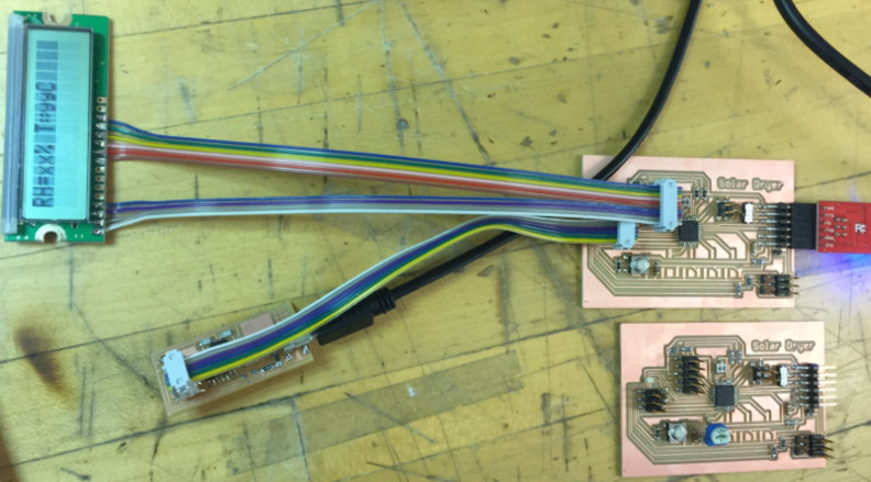
responding as I want it. Next I connected the LCD screen to a 2X5 header
where the first four pins are connected and soldered to the first four ribbon
cable wires, and then the 3rd to last 6 LCD pins were also
soldered into 6 ribbon cable wires. The next step is to just go back to your
schematic, and keep record of the arduino pin
numbers for each LCD wire connection. Then, following the directions from
this quick tutorial http://arduino.cc/en/Reference/LiquidCrystalConstructor
you can include the LCD library in Arduino,
and write a new script as shown here, subbing in the corresponding arduino pin numbers in the syntax of: LiquidCrystal(rs,
enable, d4, d5, d6, d7) Compile and verify the script is correct, run the bootloader, and then upload with programmer. Success! I got the board to say “Hello, world!” This is a good initial step, and in the future, this
LCD screen will be utilized for displaying outputs on the relative humidity
and temperature. Thus, I created a template for output and printed it on the
board as shown, which will update in the future once I’ve programmed the
reading from the temperature/humidity sensor on the 2X2 sensor pin shown
connected here:
Given the shear amount of time already spent on this
large complicated board already, the last remaining output part to explore is
the output of the fans. For simplicity, I wired up only fan 1 as just a proof
of concept, using the 2X3 header where pin 1 connects to the negative side of
the fan, pin 2 to the positive side of the fan, pin 5 to the ground of the
power supply (or car battery if you have one available for testing), and pin
6 to the 12V side of the power supply. Note, if
testing with a car battery, it’s beset to install an in-line fuse next to the
12V terminal of the battery just in case any shorting occurs. To test the concept, I wrote a sketch in arduino that turns the fan 1 pin on (pin 10) for 3
seconds, and then off for 3 seconds to replicate a 50% duty cycle but also give
it enough time to spool up. The code is here: #include <LiquidCrystal.h> LiquidCrystal lcd(4, 3, 5, 6, 7, 8); void setup() { // initialize
digital pin 10 as an output. pinMode(10, OUTPUT); pinMode(13, OUTPUT); lcd.begin(16,1); lcd.print("RH=xx% T=yyC"); } // the loop function runs over and over again
forever void loop() { digitalWrite(10, HIGH); // turn the fan on (HIGH is the
voltage level) digitalWrite(13, HIGH); // turn the LED on as well lcd.print("Speeding Up..."); delay(3000);
// wait 3000 ms digitalWrite(10, LOW); // turn the fan off by
making the voltage LOW digitalWrite(13, LOW); // turn the LED off by
making the voltage LOW lcd.print("Slowing Down..."); delay(3000);
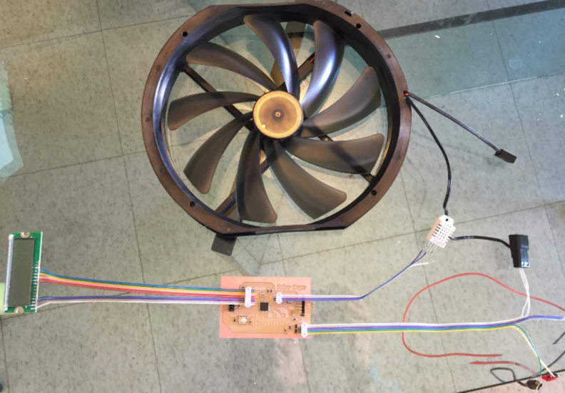
// wait 3000 ms } The code actually powers all three things at once:
Fan 1, LED, and LCD Screen. Everything worked, and sure enough the LED
flashed in synced with the speed up and slowing down of the fan. The LCD
screen however suffered a delay which will have to
be debugged later. Here is the complete setup.
A video of the testing: Solar Dryer Test 1 from Rich Li on Vimeo. Next
Steps Now that I verified that the individual outputs do work,
the next series of tests and coding will involve: 1.
Programming
adjustment of fan PWM duty cycle via turning of the potentiometer connected
on one of the ADV pins of the MCU. 2.
Calling the
right Arduino libraries to access the
temperature/humidity data from sensor, and print them on the LCD screen. 3.
Code in
temperature/humidity thresholds for fan on dependent on potentiometer, and
wire everything up into a Solar Dryer! |
|
|
|
|
|
|
|
|
|
|
|
|
|
|
|
|
|
|
|
|
