|
|
MAS.863 How To Make (Almost) Anything
– Fall 2014 Richard Li Interfaces and Applications Week 12 Up until now the interfacing with the boards have been primarily done
through the serial monitor in Arduino. This week,
it’s of interest to expand beyond that use programs like Python to build a
GUI in order to better interface with the user. I’ve never made a GUI with
Python before, so this as fun and simple exercise in make a functional GUI
with the help of Tkinter. With two weeks left to go with the final project, I am converging on
the idea of building on a smart / high tech ukulele that can teach you songs
utilizing the flashing of LEDs on the fret boards. More will come in the
coming two weeks as I work towards this! In the mean time, it’s important to
start with the fundamentals – being able to control an LED on/off
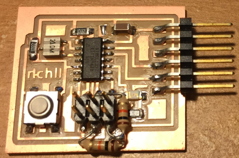
through a GUI. Arduino Programming Since the exercise focuses on being able to control an LED, any of my
previous boards will do. A good starting point was my embedded programming
week board which has served reliably in previous
weeks.
We need to program the ATTiny44 MCU on this board to receive instructions
from the computer and turn the LED on or off. The LED is connected to pin 3
in Arduino, and a simple program to receive
instruction is shown here: #include <SoftwareSerial.h> SoftwareSerial pSerial(0,1); // Initialize serial port
to Bluetooth on pins 1, 0 (RXD,
TXD) // the setup function runs once when you press reset or power
the board void setup() { // initialize
digital pin 3 as an output. pinMode(3,
OUTPUT); pinMode(8,
INPUT); //Set
pin number for Button press input pSerial.begin(9600); //Initialize Serial port to
computer } // the loop function runs over and over again forever void loop() { if (pSerial.available()) { char
c = pSerial.read(); if
(c == 'H') { digitalWrite(3, HIGH); } else
if (c == 'L') { digitalWrite(3, LOW); } pSerial.println(c); } } The code is quite simple: First we create a serial port pSerial and have pin 0 (connected to the TXD of the FTDI
cable) be the RXD for this serial port, and pin 1 be
the TXD. Next we make sure to specify pin 3 as the output pin for our LED
(see schematic), and then we have in our loop reading the data coming in the
serial port and turning on the LED when it sees a string “H” and turning off
when it sees the string “L”.
Thus, our GUI program will have to be able to send “H” and “L” to the
serial port in order to toggle the LED on. With the Arduino program written up, we
make sure to choose the correct programmer (USBTiny
in this case), and serial port before uploading it to the MCU. Note again to
pay attention to the baud rate and make sure your serial monitor baud rate is
9600 just as specified in the arduino code line
with the begin statement. Python GUI There are mainly two things the Python script has to do. First it has
to open up the same serial port that is connected to the MCU, and secondly,
it must ruin a GUI and update it based on the state of the serial port. It is important to note that I am using Python 2.7
as there is an abundance of documentation for that version. Different
commands and packages such as Tkinter have changed
resulting in discrepancies in syntax. Thus to follow along, it is best to use
this older version. Opening up a serial port in Python is quite simple. Using any kind of
editor – I’m just using the IDLE for Python on Mac – I create a
new LEDTest3.py file. The steps for opening the serial port is just importing
serial, specifying the serial port and baudrate,
and then using the .write function in order to send “H”
and “L” to trigger the on and off LED states respectively. Here is the final
code: from Tkinter
import * root = Tk()
#Makes the window root.wm_title("LED Control Panel") #Makes the title that will appear in the
top left root.config(background =
"#FFFFFF") #sets background color to white #widgets: #Left Frame and
its contents leftFrame = Frame(root,
width=200, height = 600) leftFrame.grid(row=0,
column=0, padx=10, pady=2) #Right Frame and
its contents rightFrame = Frame(root,
width=200, height = 600) rightFrame.grid(row=0, column=1, padx=10, pady=2) #Canvas for
drawing circles circleCanvas = Canvas(rightFrame, width=100, height=100, bg='white') circleCanvas.grid(row=1, column=0, padx=10, pady=2) #Logging LED
on/off status LEDLog = Text(rightFrame, width = 30, height = 10, takefocus=0) LEDLog.grid(row=3, column=0, padx=10, pady=2) #Labels firstLabel = Label(leftFrame, text="LED Toggle") firstLabel.grid(row=0, column=0, padx=10, pady=2) secondLabel = Label(rightFrame, text="Status History") secondLabel.grid(row=2, column=0, padx=10, pady=2) thirdLabel = Label(rightFrame, text="LED Visual Status") thirdLabel.grid(row=0, column=0, padx=10, pady=2) #Drawing circles
for the LED visual status def grnCircle(): circleCanvas.create_oval(20, 20, 80, 80, width=0,
fill='green') LEDLog.insert(0.0,
"On\n") def whtCircle(): circleCanvas.create_oval(19, 19, 81, 81, width=0,
fill='white') LEDLog.insert(0.0,
"Off\n") import serial import time #Open serial
port to the board arduino = serial.Serial('/dev/tty.usbserial-A987VX1H', 9600) time.sleep(2) # waiting
for initialization... print("initialising") #Turning LED on def LEDOn(): arduino = serial.Serial('/dev/tty.usbserial-A987VX1H', 9600) arduino.write("H") grnCircle() #Turning LED off def LEDOff(): arduino = serial.Serial('/dev/tty.usbserial-A987VX1H', 9600) arduino.write("L") whtCircle() #LED on/off
buttons newButton = Button(leftFrame, text="LED On", command=LEDOn) newButton.grid(row=2,
column=0, padx=10, pady=2) newButton = Button(leftFrame, text="LED Off", command=LEDOff) newButton.grid(row=3,
column=0, padx=10, pady=2) arduino.close() #close serial
port root.mainloop() #loop to
update GUI To get more information on opening serial ports using Python, you can
check out this great tutorial: http://hacknmake.blogspot.com/2013/07/control-led-with-arduino-and-python.html
http://robotic-controls.com/learn/python-guis/basics-tkinter-gui If we look at the code above, the key things are to import Tkinter, create a window and title and then add in your
widgets. At the end of the code, be sure to include the mainloop() function to so
that the GUI updates. The widgets are what really pop up as individual
modules in our windows. Here we divide up the window into left and right
frames, and have the label and button widgets on the left side, and then the
canvas for circle drawing as well as print out status on the right side. Each
frame can have a grid, and your widgets can be positioned in those grids by
specifying the row and column numbers (starting with 0). After positioning the buttons, we can label them by modifying the
text= and then specify the function that will be called when the button is
clicked by entering it after the “command=”. Of course, we’ll have to def a function, which I called LEDOn
for instance, that then proceeds to open the serial port and write “H” to it
before calling the grnCircle() function, which is another function that draws a green
circle, and then call the LEDLog widget, in which the
insert command can print the “on” string the status history on the right
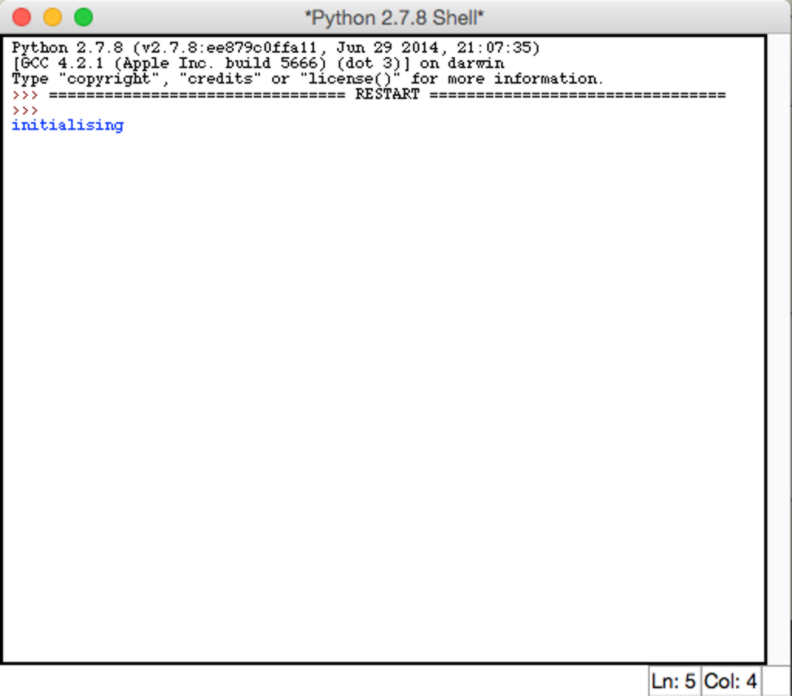
frame. The same is done for the LED Off button case, with its own separate LEDOff function and whtCircle() function which erases it. To run the program, and see the layout, simply go to the toolbar in
IDLE, click on Run and Run Module. If no errors are present, the Python shell
terminal should open up and print “initializing”:
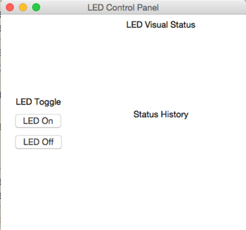
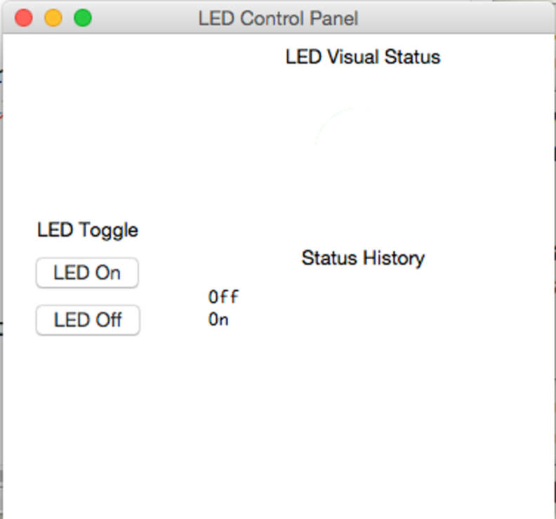
After a two second wait, the actual Tkinter
GUI will pop up:
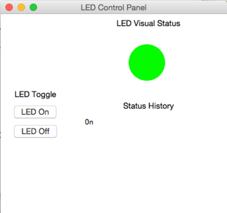
Clicking on the LED On will pop up the green circle:
And then clicking the LED Off will erase it, but still log it in the
status history.
More importantly, your board LED should also turn on and off in sync
with the visual status. Try playing around with the ON and OFF repeatedly and
you’ll see that the lights stay on with the visual status circles. If the LED
is not syncing, then there is an issue with the serial port write function
not being able to write “H” or “L”’s over. Check all hardware connections,
and that your board was programmed correctly in Arduino.
As a good debugging tactic, open up the serial monitor in Arduino,
and type in H. The LED should turn on. If not, then there is something wrong
with the Arduino code in being able to read the
transmitted serial input. As always, add in some pserial.println(); lines
to help figure out whether parts of the loop or if statements are being
entered. Here is the video of it in action: LED Controller - Python/Tkinter from Rich Li on Vimeo. That’s it! Short and sweet, but good initial fundamentals for LED
controller and drawing a visual indicator GUI in Tkinter/Python.
This will serve as the basis for the final project as I envision drawing up
either virtual frets or some sort of LED indicator for getting chord shapes
of the ukulele to light up. |
|
|
|
|
|
|
|
|
|
|
|
|
|
|
|
|
|
|
|
|